Asus PSCH-SR SATA PSCH-SR User Manual English Version - Page 24
Layout contents
 |
View all Asus PSCH-SR SATA manuals
Add to My Manuals
Save this manual to your list of manuals |
Page 24 highlights
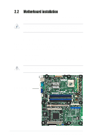
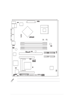
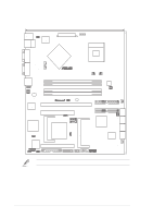
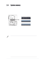
2.2.4 Layout contents Slots Page 1. DDR DIMM 2-11 2. PCI 2-16 Jumpers 1. Keyboard power (3-pin KBPWR1) 2-17 2. Integrated LAN controllers (3-pin LAN_EN1; LAN_EN2) 2-17 3. Integrated graphics controller (3-pin VGA_EN1) 2-18 4. SATA/SCSI jumper controller (3-pin SASI_EN1) 2-18 5. Clear RTC RAM (3-pin CLRTC1) 2-19 6. Force BIOS recovery (3-pin J5) 2-20 7. Hard disk drive/SCSI LED switch (4-pin J4) 2-20 8. DDR voltage regulator (3-pin J6) 2-21 9. Serial ROM initialization jumper (3-pin J2) 2-21 Rear panel connectors 1. PS/2 mouse port 2. LAN1 port 3. LAN2 port 4. VGA port 5. Serial port 6. USB 2.0 ports 1 and 2 7. PS/2 keyboard port 2-22 2-22 2-22 2-22 2-22 2-2223 2-22 Internal connectors 1. Power supply unit SMBus connector (5-pin PSUSMB1) 2-23 2. Front panel SMBus connector (6-1 pin FPSMB1 [white]) 2-23 3. Backplane SMBus connector (6-1 pin BPSMB1 [black]) 2-24 4. Chassis intrusion connector (4-1 pin CHASSIS1) 2-24 5. IDE connectors (40-1 pin PRI_IDE1 [blue], SEC_IDE1 [black) 2-25 6. Serial ATA connectors (7-pin SATA1, SATA2) 2-26 7. Serial ATA RAID connectors (7-pin SATA_RAID1, 2-27 SATA_RAID2, SATA_RAID3, SATA_RAID4) 8. LAN LED connector (4-pin LAN_LED1) 2-27 9. ATX power connectors (20-pin ATXPWR1, 4-pin ATX12V1) 2-28 10. Floppy disk drive connector (34-1 pin FLOPPY1) 2-28 11. Ultra320 SCSI connector (68-pin SCSIA1) 2-29 12. Locator connector (6-pin LOCATOR) 2-29 13. CPU, Front, and Rear Fan connectors 2-30 (3-pin CPU_FAN1/2, FRONT_FAN1/2, REAR_FAN1/2) 14. Serial connector (10-1 pin COM2 for management use) 2-30 15. System panel connector (20-1 pin PANEL) 2-31 2-6 Chapter 2: Hardware information
-
 1
1 -
2
-
3
-
4
-
5
-
6
-
7
-
8
-
9
-
10
-
11
-
12
-
13
-
14
-
15
-
16
-
17
-
18
-
 19
19 -
 20
20 -
 21
21 -
 22
22 -
 23
23 -
 24
24 -
 25
25 -
 26
26 -
 27
27 -
 28
28 -
 29
29 -
30
-
31
-
32
-
33
-
34
-
35
-
36
-
37
-
38
-
39
-
40
-
41
-
42
-
43
-
44
-
45
-
46
-
47
-
48
-
49
-
50
-
51
-
52
-
53
-
54
-
55
-
56
-
57
-
58
-
59
-
60
-
61
-
62
-
63
-
64
-
65
-
66
-
67
-
68
-
69
-
70
-
71
-
72
-
73
-
74
-
75
-
76
-
77
-
78
-
79
-
80
-
81
-
82
-
83
-
84
-
85
-
86
-
87
-
88
-
89
-
90
-
91
-
92
-
93
-
94
-
95
-
96
-
97
-
98
-
99
-
100
-
101
-
102
 |
 |
