Asus PSCH-SR SATA PSCH-SR User Manual English Version - Page 42
Hardware information, Backplane SMBus connector 6-1 pin BPSMB1 [black], Chassis intrusion - psch sr 24 sata
 |
View all Asus PSCH-SR SATA manuals
Add to My Manuals
Save this manual to your list of manuals |
Page 42 highlights
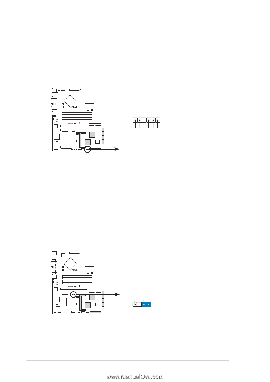
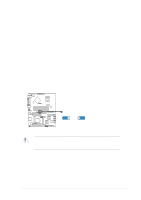
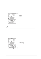
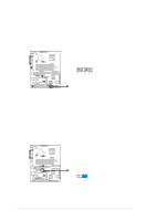
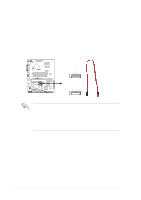
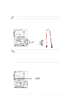
3. Backplane SMBus connector (6-1 pin BPSMB1 [black]) This connector allows you to connect SMBus (System Management Bus) devices to system backplane components such as SATA or SCSI backplanes. Devices communicate with an SMBus host and/or other SMBus devices using the SMBus interface. ® PSCH-SR BPSMB1 1 FAN_PWM I2C_6_CLK# GND I2C_6_DATA# +5V PSCH-SR Backplane SMBus Header 4. Chassis intrusion connector (4-1 pin CHASSIS1) This lead is for a chassis designed with intrusion detection feature. This requires an external detection mechanism such as a chassis intrusion sensor or microswitch. When you remove any chassis component, the sensor triggers and sends a high-level signal to this lead to record a chassis intrusion event. By default, the pins labeled "Chassis Signal" and "Ground" are shorted with a jumper cap. If you wish to use the chassis intrusion detection feature, remove the jumper cap from the pins. ® PSCH-SR CHASSIS1 +5VSB CASEOPEN GND (Default) PSCH-SR Chassis Intrusion Connector 2-24 Chapter 2: Hardware information
-
 1
1 -
2
-
3
-
4
-
5
-
6
-
7
-
8
-
9
-
10
-
11
-
12
-
13
-
14
-
15
-
16
-
17
-
18
-
19
-
20
-
21
-
22
-
23
-
24
-
25
-
26
-
27
-
28
-
29
-
30
-
31
-
32
-
33
-
34
-
35
-
36
-
 37
37 -
 38
38 -
 39
39 -
 40
40 -
 41
41 -
 42
42 -
 43
43 -
 44
44 -
 45
45 -
 46
46 -
 47
47 -
48
-
49
-
50
-
51
-
52
-
53
-
54
-
55
-
56
-
57
-
58
-
59
-
60
-
61
-
62
-
63
-
64
-
65
-
66
-
67
-
68
-
69
-
70
-
71
-
72
-
73
-
74
-
75
-
76
-
77
-
78
-
79
-
80
-
81
-
82
-
83
-
84
-
85
-
86
-
87
-
88
-
89
-
90
-
91
-
92
-
93
-
94
-
95
-
96
-
97
-
98
-
99
-
100
-
101
-
102
 |
 |