Asus PSCH-SR SATA PSCH-SR User Manual English Version - Page 49
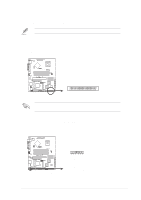
ATX Power Switch/Soft-Off Switch 2-pin PWR_SW
 |
View all Asus PSCH-SR SATA manuals
Add to My Manuals
Save this manual to your list of manuals |
Page 49 highlights
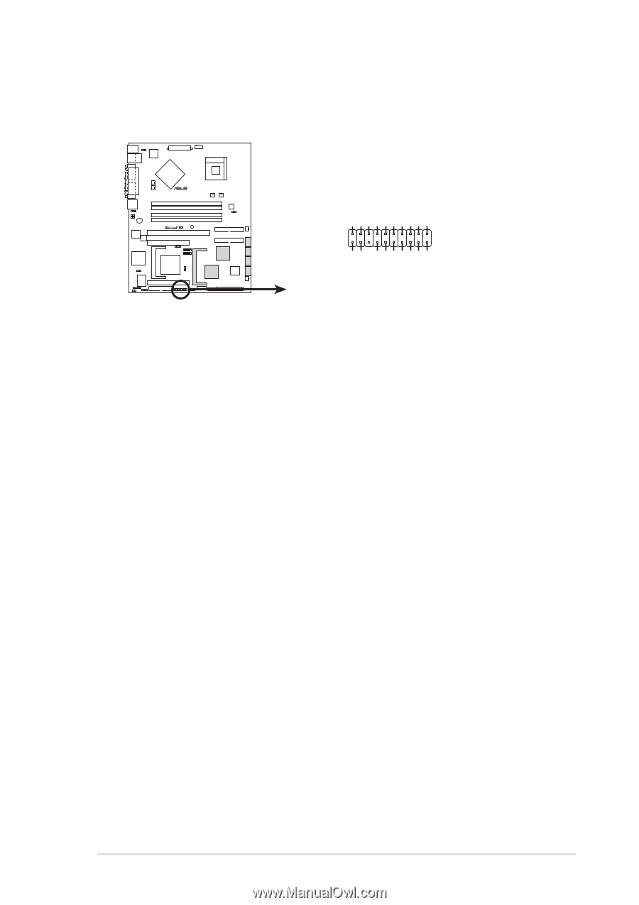
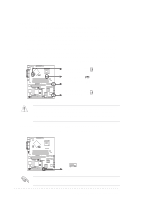
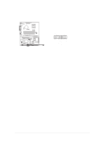
15. System panel connector (20-1 pin PANEL) This connector accommodates several system front panel functions. POWERLED+ NC POWERLEDMLED+ MLEDNC +5V GND GND SPKROUT ® PSCH-SR PANEL1 HDLED+ HDLEDNMIBTN# GND POWERBTN# GND NC RESETBTN# GND PSCH-SR System Panel Connector • System Power LED (3-pin PLED) This connector is for the system power LED. The LED lights up when you turn on the system power, and blinks when the system is in sleep mode. • Message LED (2-pin MLED) This connector is for the front panel message LED that indicates the booting status. The LED blinks when the system is in the boot process until the operating system is loaded. • System Warning Speaker (4-pin SPKR) This connector is for the case-mounted speaker and allows you to hear system beeps and warnings. • Hard Disk Activity (2-pin HD_LED) This connects to the hard disk drive LED. The read or write activities of the hard disk drive connected to the any of IDE connectors cause the hard disk drive LED to light up. • ATX Power Switch/Soft-Off Switch (2-pin PWR_SW) This connector is for the system power switch. Pressing the power switch turns the system between ON and SLEEP, or ON and SOFT OFF, depending on the BIOS or OS settings. Pressing the power switch for more than 4 seconds when the system is on turns the system off. • Reset Switch (2-pin RESET) This connector is for the case-mounted reset switch for rebooting the system without turning off the system power. ASUS PSCH-SR motherboard 2-31
-
 1
1 -
2
-
3
-
4
-
5
-
6
-
7
-
8
-
9
-
10
-
11
-
12
-
13
-
14
-
15
-
16
-
17
-
18
-
19
-
20
-
21
-
22
-
23
-
24
-
25
-
26
-
27
-
28
-
29
-
30
-
31
-
32
-
33
-
34
-
35
-
36
-
37
-
38
-
39
-
40
-
41
-
42
-
43
-
 44
44 -
 45
45 -
 46
46 -
 47
47 -
 48
48 -
 49
49 -
 50
50 -
 51
51 -
 52
52 -
 53
53 -
 54
54 -
55
-
56
-
57
-
58
-
59
-
60
-
61
-
62
-
63
-
64
-
65
-
66
-
67
-
68
-
69
-
70
-
71
-
72
-
73
-
74
-
75
-
76
-
77
-
78
-
79
-
80
-
81
-
82
-
83
-
84
-
85
-
86
-
87
-
88
-
89
-
90
-
91
-
92
-
93
-
94
-
95
-
96
-
97
-
98
-
99
-
100
-
101
-
102
 |
 |