Asus PSCH-SR SATA PSCH-SR User Manual English Version - Page 48
Pin Cpu_fan1/2, Front_fan1/2, Rear_fan1/2
 |
View all Asus PSCH-SR SATA manuals
Add to My Manuals
Save this manual to your list of manuals |
Page 48 highlights
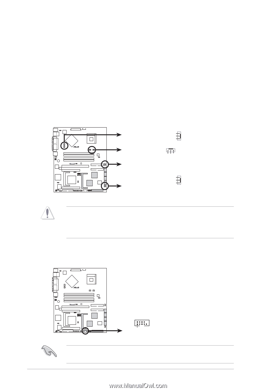
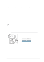
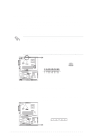
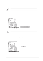
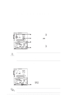
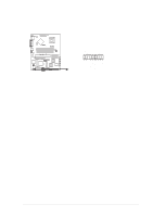
13. CPU, Front, and Rear fan connectors (3-pin CPU_FAN1/2, FRONT_FAN1/2, REAR_FAN1/2) The fan connectors on this motherboard support various server configurations. Use the rear fan connectors if you intend to install the motherboard in a tower/pedestal chassis. Use the front fan connectors when using a rackmount configuration. The fan connectors support cooling fans of 350 mA ~ 740 mA (8.88 W max.) or a total of 1 A ~ 2.22 A (26.64 W max.) at +12 V. Connect the fan cables to the fan connectors on the motherboard, making sure that the black wire of each cable matches the ground pin of the connector. ® PSCH-SR REAR_FAN1 Speed Power REAR_FAN2 GND CPU_FAN1 CPU_FAN2 Speed Power GND FRONT_FAN1 Speed FRONT_FAN2 Power GND PSCH-SR Fan Connectors Do not forget to connect the fan cables to the fan connectors. Lack of sufficient air flow within the system may damage the motherboard components. These are not jumpers! DO NOT place jumper caps on the fan connectors! 14. Serial connector (10-1 pin COM2 for management use) This connector accommodates a server management card using the serial interface. ® PSCH-SR COM2 PIN 1 PSCH-SR Serial COM2 Bracket Since this connector is dedicated for server management, you must use a null modem cable to make the connector operational. 2-30 Chapter 2: Hardware information
-
 1
1 -
2
-
3
-
4
-
5
-
6
-
7
-
8
-
9
-
10
-
11
-
12
-
13
-
14
-
15
-
16
-
17
-
18
-
19
-
20
-
21
-
22
-
23
-
24
-
25
-
26
-
27
-
28
-
29
-
30
-
31
-
32
-
33
-
34
-
35
-
36
-
37
-
38
-
39
-
40
-
41
-
42
-
 43
43 -
 44
44 -
 45
45 -
 46
46 -
 47
47 -
 48
48 -
 49
49 -
 50
50 -
 51
51 -
 52
52 -
 53
53 -
54
-
55
-
56
-
57
-
58
-
59
-
60
-
61
-
62
-
63
-
64
-
65
-
66
-
67
-
68
-
69
-
70
-
71
-
72
-
73
-
74
-
75
-
76
-
77
-
78
-
79
-
80
-
81
-
82
-
83
-
84
-
85
-
86
-
87
-
88
-
89
-
90
-
91
-
92
-
93
-
94
-
95
-
96
-
97
-
98
-
99
-
100
-
101
-
102
 |
 |