Asus S-presso Spresso Hardware User Manual - Page 52
Required IDE Configuration settings in BIOS
 |
View all Asus S-presso manuals
Add to My Manuals
Save this manual to your list of manuals |
Page 52 highlights
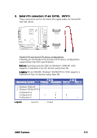
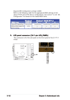
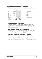
Required IDE Configuration settings in BIOS Refer to the following table for the appropriate BIOS settings of the above P-ATA and S-ATA device configurations. See section "5.3. 5 IDE Configuration" for details on the related BIOS items. BIOS item W i n d o w s® 2000/XP W i n d o w s® 9 8 / M E / N T 4 . 0 A B C Onboard IDE Operate Mode Enhanced Mode Compatible Mode Compatible Mode Compatible Mode Enhanced Mode Support On S-ATA - - - IDE Port Settings - Primary P-ATA+S-ATA Sec. P-ATA+S-ATA P-ATA Ports Only 9 . LCD panel connector (24-1-pin LCD_PANEL) This connector is for the LCD panel on the front panel of the S1-P111 model. P4P8T ® P4P8T LCD_PANEL connector LCD_PANEL +5VSB PIC_STB# PIC_CLK PIC_CLK PIC_STB# DJ_PLAY DJ_SCANFW SMBDATA SMBCLK DJ_VOLUP DJ_STOP# GND PIC_DOUT PIC_DIN PIC_DIN PIC_DOUT +5V DJ_SCANRW +5VSB GND +12V DJ_VOLDN 3-10 Chapter 3: Motherboard info
-
 1
1 -
2
-
3
-
4
-
5
-
6
-
7
-
8
-
9
-
10
-
11
-
12
-
13
-
14
-
15
-
16
-
17
-
18
-
19
-
20
-
21
-
22
-
23
-
24
-
25
-
26
-
27
-
28
-
29
-
30
-
31
-
32
-
33
-
34
-
35
-
36
-
37
-
38
-
39
-
40
-
41
-
42
-
43
-
44
-
45
-
46
-
 47
47 -
 48
48 -
 49
49 -
 50
50 -
 51
51 -
 52
52 -
 53
53 -
 54
54 -
 55
55 -
 56
56 -
 57
57 -
58
-
59
-
60
-
61
-
62
-
63
-
64
-
65
-
66
-
67
-
68
-
69
-
70
-
71
-
72
-
73
-
74
-
75
-
76
-
77
-
78
-
79
-
80
-
81
-
82
-
83
-
84
-
85
-
86
-
87
-
88
-
89
-
90
-
91
-
92
-
93
-
94
-
95
-
96
-
97
-
98
-
99
-
100
-
101
-
102
-
103
-
104
-
105
-
106
 |
 |
