Asus TUWE-M TUWE-M User Manual - Page 31
Three 1/8 Line_In, Line_Out, Mic optional
 |
View all Asus TUWE-M manuals
Add to My Manuals
Save this manual to your list of manuals |
Page 31 highlights
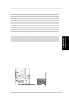
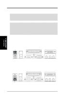
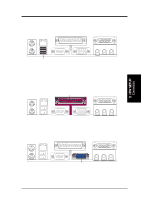
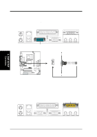
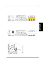
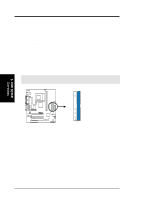
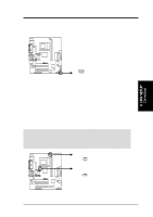
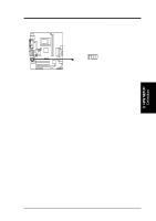
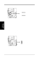
3. HARDWARE SETUP 8) Audio Port Connectors (Three 1/8" Line_In, Line_Out, Mic) (optional) Line Out (lime) can be connected to headphones or preferably powered speakers. Line In (light blue) allows tape players or other audio sources to be recorded by your computer or played through the Line Out (lime). Mic (pink) allows microphones to be connected for inputting voice. See Section 6.3 in Software Reference, Multi-Channel Audio Feature Setup for information about using Line Out, Line In and Mic for audio output. Line Out Line In Mic 1/8" Stereo Audio Connectors 9) Fast-Ethernet Port Connector (RJ45) (optional) The RJ45 connector is located on top of the USB Ports 0 & 1. The connector allows the motherboard to connect to a Local Area Network (LAN) through a network hub. RJ-45 3. H/W SETUP DCMoAnnCehcatnornsels 10) Floppy Disk Drive Connector (34-1pin FLOPPY) This connector supports the provided floppy drive ribbon cable. After connecting the single end to the board, connect the two plugs on the other end to the floppy drives. (Pin 5 is removed to prevent inserting in the wrong orientation when using ribbon cables with pin 5 plugged). FLOPPY ® TUWE-M NOTE: Orient the red markings on the floppy ribbon cable to PIN 1. PIN 1 TUWE-M Floppy Disk Drive Connector ASUS TUWE-M User's Manual 31
-
 1
1 -
2
-
3
-
4
-
5
-
6
-
7
-
8
-
9
-
10
-
11
-
12
-
13
-
14
-
15
-
16
-
17
-
18
-
19
-
20
-
21
-
22
-
23
-
24
-
25
-
 26
26 -
 27
27 -
 28
28 -
 29
29 -
 30
30 -
 31
31 -
 32
32 -
 33
33 -
 34
34 -
 35
35 -
 36
36 -
37
-
38
-
39
-
40
-
41
-
42
-
43
-
44
-
45
-
46
-
47
-
48
-
49
-
50
-
51
-
52
-
53
-
54
-
55
-
56
-
57
-
58
-
59
-
60
-
61
-
62
-
63
-
64
-
65
-
66
-
67
-
68
-
69
-
70
-
71
-
72
-
73
-
74
-
75
-
76
-
77
-
78
-
79
-
80
-
81
-
82
-
83
-
84
-
85
-
86
-
87
-
88
-
89
-
90
 |
 |
