Asus TUWE-M TUWE-M User Manual - Page 36
ASUS TUWE-M User's Manual, LCD-TV Headers 18-pin, 18-1 pin LCD TV, USB Header 10-1 pin USB2
 |
View all Asus TUWE-M manuals
Add to My Manuals
Save this manual to your list of manuals |
Page 36 highlights
3. HARDWARE SETUP 17) LCD-TV Headers (18-pin, 18-1 pin LCD TV) These headers require optional modules for LCD or TV output. LCDTV ® TUWE-M 1 TUWE-M LCD-TV Headers 3. H/W SETUP Connectors 18) USB Header (10-1 pin USB2) If the USB Ports on the back panels are inadequate,one USB header is available for two additional USB ports. Connect the 10-pin ribbon cables from the provided 2-port USB connector set to the two midboard 10-pin USB headers and mount the USB connector set to an open slot on your chassis. ® TUWE-M TUWE-M USB Headers USB2 5 10 1: USB Power 2: USBP2- 3: USBP2+ 4: GND 5: NC 6: USB Power 7: USBP3- 8: USBP3+ 9: GND 16 36 ASUS TUWE-M User's Manual
-
 1
1 -
2
-
3
-
4
-
5
-
6
-
7
-
8
-
9
-
10
-
11
-
12
-
13
-
14
-
15
-
16
-
17
-
18
-
19
-
20
-
21
-
22
-
23
-
24
-
25
-
26
-
27
-
28
-
29
-
30
-
 31
31 -
 32
32 -
 33
33 -
 34
34 -
 35
35 -
 36
36 -
 37
37 -
 38
38 -
 39
39 -
 40
40 -
 41
41 -
42
-
43
-
44
-
45
-
46
-
47
-
48
-
49
-
50
-
51
-
52
-
53
-
54
-
55
-
56
-
57
-
58
-
59
-
60
-
61
-
62
-
63
-
64
-
65
-
66
-
67
-
68
-
69
-
70
-
71
-
72
-
73
-
74
-
75
-
76
-
77
-
78
-
79
-
80
-
81
-
82
-
83
-
84
-
85
-
86
-
87
-
88
-
89
-
90
 |
 |

36
ASUS TUWE-M User’s Manual
Connectors
3. H/W SETUP
3. HARDWARE SETUP
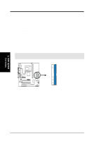
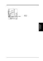
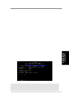
17) LCD-TV Headers (18-pin, 18-1 pin LCD TV)
These headers require optional modules for LCD or TV output.
TUWE-M
®
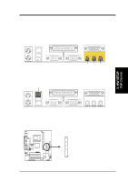
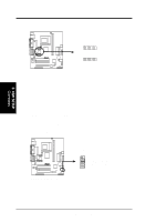
TUWE-M USB Headers
USB2
1
5
6
10
1: USB Power
2: USBP2–
3: USBP2+
4: GND
5: NC
6: USB Power
7: USBP3–
8: USBP3+
9: GND
TUWE-M
®
TUWE-M LCD-TV Headers
1
LCDTV
18) USB Header (10-1 pin USB2)
If the USB Ports on the back panels are inadequate,one USB header is available
for two additional USB ports. Connect the 10-pin ribbon cables from the pro-
vided 2-port USB connector set to the two midboard 10-pin USB headers and
mount the USB connector set to an open slot on your chassis.