Behringer ODYSSEY Quick Start Guide - Page 8
Step 2: Controls - sequencer
 |
View all Behringer ODYSSEY manuals
Add to My Manuals
Save this manual to your list of manuals |
Page 8 highlights
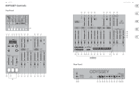
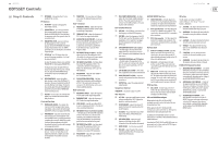
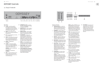
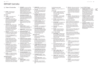
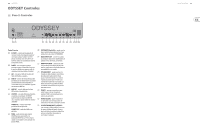
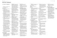
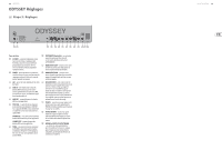
14 ODYSSEY ODYSSEY Controls (EN) Step 2: Controls (1) KEYBOARD - the keyboard has 37 semiweighted, full-size keys. FX Section (2) FX ON/OFF - engage or disengage the Klark Teknik FX circuit. (3) PARAMETER 1/2- press once to show the first parameter of the current FX program. Rotate the PROGRAM/VALUE knob to adjust the parameter value. Press again to show the second parameter. (4) PARAMETER 3 (TAP)- press once to show the third parameter of the current FX program. Rotate the PROGRAM/VALUE knob to adjust the parameter value. For TEMPO parameters, you can also tap this switch at the required tempo. (5) FX DISPLAY- this LCD display shows the current FX program, parameters 1 to 3, and the values and units. To adjust the display contrast, press and hold PARAMETER 1/2 while tapping PARAMETER 3. The display also shows the audio level bars along the right edge. If the top "OL" overload bar is lit, adjust the AUDIO MIXER fader(s) or VCA fader to prevent overloading and distortion. (6) PROGRAM/VALUE- rotate this endless push-encoder to select from 32 different FX programs, then press the knob to load the FX currently flashing in the display. This knob is also used to adjust the value of the different parameters of each FX after a PARAMETER switch has been pressed. (7) FX SEND- rotate to adjust the amount of FX added, from minimum to maximum effect (fully clockwise). Controls Section (8) TEMPO/GATE LENGTH - this controls the sequencer and the arpeggio tempo. During step editing, it also controls the GATE length, and if SHIFT is held, it also adjusts the SWING. (9) PORTAMENTO - adjust the amount of glide time between notes on the keyboard. If the recessed MODE switch is pressed, portamento is enabled when using the TRANSPOSE switch; if released, then portamento is disabled. An optional footswitch can be used to engage or disengage portamento. (10) PROPORTIONAL PITCH CONTROL - these pressure-sensitive soft pads allow you to adjust the pitch lower, or higher, or to add LFO modulation. Press harder to increase the effect. (11) TRANSPOSE - this 3-position switch allows you to move the keyboard range up or down 2 octaves. VCO-1 Section (12) FREQUENCY COARSE - adjust the frequency of Voltage Controlled Oscillator 1 (VCO-1) with a wide range of adjustment. (13) FREQUENCY-FINE - adjust the frequency of VCO-1 with a fine range of adjustment. (14) AUDIO KYBD ON/LF KYBD OFF - In the top position, the ODYSSEY and keyboard function as normal. In the bottom position, VCO-1 is reduced to a low frequency, unaffected by the keyboard. Adjust using the VCO-1 frequency faders. (15) FM FADER (LFO sine or square) - the fader adjusts the level of FM modulation of VCO-1. The switch selects between LFO sine or square wave as the source of FM modulation. (16) FM FADER (S/H or ADSR) - the fader adjusts the level of FM modulation of VCO-1. The switch selects between S/H (Sample and Hold) or the ADSR envelope as the source of FM modulation. (17) PULSE WIDTH - adjust the pulse width of VCO-1 from square (50%). (18) PULSE WIDTH MODULATION - the fader adjusts the level of pulse width modulation of VCO-1. The switch selects between LFO sinewave or the ADSR envelope as the source of pulse width modulation. VCO-2 Section (19) FREQUENCY COARSE - adjust the frequency of VCO-2 with a wide range of adjustment. (20) FREQUENCY-FINE - adjust the frequency of VCO-2 with a fine range of adjustment. (21) SYNC ON/OFF - turn this on to allow VCO-2 to sync its frequency with VCO-1. (Turn this off when using Ring Modulation.) (22) FM FADER (LFO sine or S/H mixer or pedal) - the fader adjusts the level of FM modulation of VCO-2. The switch selects between LFO sinewave or the S/H Mixer or Pedal as the source of FM modulation. An optional foot pedal can be connected to the rear panel. (23) FM FADER (S/H or ADSR) - the fader adjusts the level of FM modulation of VCO-2. The switch selects between S/H or the ADSR envelope as the source of FM modulation. (24) PULSE WIDTH - adjust the pulse width of VCO-2 from square (50%). Quick Start Guide 15 (25) PULSE WIDTH MODULATION - the fader adjusts the level of pulse width modulation of VCO-2. The switch selects between LFO sinewave or the ADSR envelope as the source of pulse width modulation. LFO and S/H Section (26) RATE LED - this LED flashes at the rate of the low frequency oscillator (LFO) frequency. (27) LFO FREQ - adjust the frequency of the LFO. The LFO can be used for FM and pulse width modulation of VCO-1 and VCO-2, to trigger the S/H, modulate the VCF, and vary the REPEAT rate. (28) S/H MIXER FADER (VCO-1 saw or pulse) - the fader adjusts the input level to the sample/hold. The switch selects between VCO-1 sawtooth or pulse waveform as the S/H input source. (29) S/H MIXER FADER (Noise or VCO-2 pulse) - the fader adjusts the input level to the S/H. The switch selects between the internal Noise or VCO-2 pulse waveform as the S/H input source. (30) S/H TRIGGER (LFO or KYBD) - select if the S/H is triggered by the LFO or by the keyboard. (31) NOISE GEN (WHITE or PINK) - select the internal noise generator between white noise or pink noise. (32) OUTPUT LAG - adjust the sample and hold output lag time. Sequencer Section SEQUENCER - see details on page 17 and 44. VCF Section (33) VCF FREQ - adjust the cutoff frequency of the voltage controlled filter (VCF). Frequencies above the cutoff are attenuated. (34) VCF RESONANCE - adjusts the amount of volume level boost (resonance) given at the cut-off frequency. (35) VCF MODE - choose from three classic filter types: 2-Pole (4023), 4-Pole (4035), and 4-Pole (4075). (36) HPF CUTOFF FREQ - adjust the cutoff frequency of the high-pass filter (HPF). Frequencies below the cutoff are attenuated. (37) DRIVE ON/OFF - turn the drive on and off. (38) VCA GAIN - adjust the gain of the voltage controlled amplifier (VCA). The output is not triggered by the keyboard. AUDIO MIXER Section (39) NOISE/ RING MOD - the fader adjusts the level of noise or ring modulation added to the overall mix. The switch selects between the internal noise generator and ring modulation. (40) VCO-1 (saw or pulse) - the fader adjusts the level of VCO-1 added to the overall mix. The switch selects between the VCO-1 sawtooth or pulse waveforms. (41) VCO-2 (saw or pulse) - the fader adjusts the level of VCO-2 added to the overall mix. The switch selects between the VCO-2 sawtooth or pulse waveforms. VCF Section (42) KYBD CV / S/H Mixer or Pedal - the fader adjusts the level of effect on the VCF. The switch selects the source affecting the VCF, either the keyboard control voltage or the S/H Mixer, or an optional pedal. (43) S/H or LFO - the fader adjusts the level of effect on the VCF. The switch selects the source affecting the VCF, either the S/H or the LFO sinewave. (44) ADSR or AR - the fader adjusts the level of effect the AR or ADSR envelopes have on the VCF. The switch selects either the ADSR or AR envelope. This switch, and a similar switch in the VCA section, allows you to control the VCF and VCA with separate envelopes if desired. VCA Section (45) AR or ADSR - the fader adjusts the level of effect the AR or ADSR envelopes have on the VCA. The switch selects either the ADSR envelope or the AR envelope. AR and ADSR Envelopes When applied to the VCA, the AR and ADSR envelopes are used to control the level of the note being played over time. When applied to the VCF, the AR and ADSR envelopes are used to control the cut-off frequency of the filter for each note played over time. In addition, the AR and ADSR envelopes can also affect the VCO-1 and VCO-2 FM modulation and pulse width modulation. Note that the ATTACK, DECAY and RELEASE stages are measured in units of time, and the SUSTAIN stage is measured in units of level. AR Section The AR controls are similar to the ADSR controls if they are set to: Decay = Zero, and Sustain = Maximum. (46) A-ATTACK - this adjusts the time for the level to reach maximum after a key is pressed. (47) R-RELEASE - this adjusts the time it takes for the signal to decay once the key is released. ADSR Section (48) A-ATTACK - this adjusts the time for the level to reach maximum after a key is pressed. (49) D-DECAY - this adjusts the time to decay down to the SUSTAIN level after the attack time is over. (50) S-SUSTAIN - this sets the sustain level reached after the attack and decay time are over. (51) R-RELEASE - this adjusts the time it takes for the signal to decay once the key is released. KYBD/LFO Repeat Section (52) ADSR KYBD GATE/LFO REPEAT - set to ADSR KYBD GATE in normal use. If set to LFO REPEAT, then notes will repeat at the tempo set by the LFO Frequency, either when a note is played, or automatically, depending on the setting of the KYBD REPEAT/AUTO REPEAT switch. (53) KYBD REPEAT / AUTO REPEAT - If either of the adjacent switches are set to LFO REPEAT, then notes will repeat at the tempo set by the LFO Frequency, either when a note is played (KYBD REPEAT position), or automatically (AUTO REPEAT position). (54) AR KYBD GATE/LFO REPEAT - set to AR KYBD GATE in normal use. If set to LFO REPEAT, then notes will repeat at the tempo set by the LFO Frequency, either when a note is played, or automatically, depending on the setting of the KYBD REPEAT/AUTO REPEAT switch.
-
 1
1 -
2
-
 3
3 -
 4
4 -
 5
5 -
 6
6 -
 7
7 -
 8
8 -
 9
9 -
 10
10 -
 11
11 -
 12
12 -
 13
13 -
14
-
15
-
16
-
17
-
18
-
19
-
20
-
21
-
22
-
23
-
24
-
25
-
26
-
27
-
28
 |
 |
