Behringer ODYSSEY Quick Start Guide - Page 9
Rear Panel, Sequencer
 |
View all Behringer ODYSSEY manuals
Add to My Manuals
Save this manual to your list of manuals |
Page 9 highlights
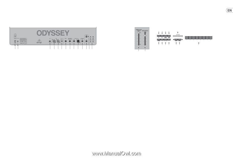
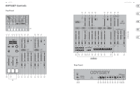
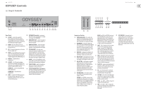
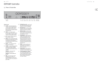
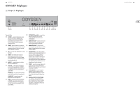
16 ODYSSEY ODYSSEY Controls (EN) Step 2: Controls (55) (56) (57) (58) (59) (60) (61) (62) (63) (64) (65) (66) (67) (68) Rear Panel (55) DC INPUT - connect the supplied DC power adapter here. The power adapter can be plugged into an AC outlet capable of supplying from 100 V to 240 V at 50 Hz/60 Hz. Use only the power adapter supplied. (62) PORTAMENTO Footswitch - an optional footswitch can be connected here, to engage or disengage the PORTAMENTO. (63) MAIN OUTPUT LOW - connect this output to the lower-level inputs of guitar amplifiers or mixers for example. (56) POWER - turn the synthesizer on or off. (64) MAIN OUTPUT HIGH - connect this output Make sure all the connections are made before to the line-level inputs of mixers, keyboard turning on the unit. amplifiers, or powered speakers for example. (57) LED - this adjusts the brightness of the fader (65) EXT AUDIO INPUT - this input can be LEDs from bright to off. connected to the line-level audio output from (58) MIDI IN - receives MIDI data from an external source. This will commonly be another MIDI keyboard, an external hardware sequencer, a computer equipped with a MIDI interface, etc. an external audio device. The level can be adjusted at the source, and it will play when the keyboard or a sequencer pattern is played. Low-level sources may need boosting to linelevel with an external pre-amplifier or mixer. (59) MIDI OUT - sends MIDI data to an application. (66) PHONES - connect your headphones to this output. Make sure the PHONES volume knob is (60) USB PORT - This USB type B jack allows turned down before putting on headphones. connection to a computer. The ODYSSEY will show up as a class-compliant USB MIDI device, capable of supporting MIDI in and out. (67) PHONES VOLUME - adjust the headphones volume to a safe level before putting on headphones or turning on the unit. USB MIDI IN - accepts incoming MIDI data from an application. (68) CV/GATE/TRIGGER INPUTS and OUTPUTS - these inputs and outputs allow the connection USB MIDI OUT - sends MIDI data to of control voltage, gate and trigger signals an application. from compatible external devices such as (61) PEDAL - an optional VOLUME footpedal can modular synthesizer equipment. be connected here, to vary the VCO-2 FM modulation and the VCF if their switches are set to the PEDAL position. Quick Start Guide 17 (3) (4) (5) (6) (11) (7) (8) (9) (10) (12) (13) (14) (1) (2) Sequencer Section (1) TEMPO/GATE LENGTH - this controls the sequencer and arpeggio tempo. During step editing, it also controls the GATE length. If SHIFT is held, then it also adjusts the SWING. (2) PORTAMENTO - during step editing, this fader can be used to add a Ratchet by splitting the current step into 1, 2, 3, or 4 parts. Hold down SHIFT and move the fader to split the current step into the number of parts shown by the LOCATOR LEDs (yellow) 1 to 4. (3) HOLD/REST - during pattern playback, this allows you to hold the current step. During step editing, it allows you to enter a rest. (4) RESET/ACCENT - during playback, this allows you to reset the pattern back to step 1. During step editing, you can add an accent to a step. (5) ARP (SET END) - In ARP mode, an arpeggio will play, based on the held notes on the keyboard. Double-press to keep playing an arpeggio when all keys are released. In Sequencer mode, pressing SHIFT and SET END together, followed by a STEP switch, will allow that step to become the end of the current pattern. (6) PATTERN (BANK) - This switch is used to access either the current pattern, or bank number, as follows: PATTERN: Press PATTERN, and one of the 8 LOCATION LEDs will show the current pattern number (from 1 to 8). To change to a different pattern number, keep PATTERN held down and press any of the STEP switches (1 to 8), or press to increase the pattern number. BANK: Press SHIFT and PATTERN, and one of the 8 LOCATION LEDs will show the current bank number (from 1 to 8). To change to a different bank number, keep both SHIFT and BANK held down, and press any of the STEP switches (1 to 8), or press to increase the bank number. (7) SHIFT - This is used to access the secondary features of some of the other sequencer controls, such as SET END, BANK, SWING, KYDB, and STEP. Hold down SHIFT and the other switch at the same time. For example SHIFT + PATTERN (BANK) will show the current BANK number in the LOCATOR LEDs. (8) PAGE - each pattern can be up to 32 steps in length. This switch allows you to show each of the 4 pages of 8 steps each. The LOCATION LEDs 1 to 4, show which page you are on. If a pattern is playing, the STEP LEDs will show the steps in use on the current page. (9) PLAY/STOP - starts or stops the playback of the pattern. If SHIFT is held at the same time, then this is the start of the pattern saving procedure, described below. (10) REC - press this to begin the recording of a new pattern. This is also used with SHIFT during the pattern saving procedure. (11) LOCATION - these multi-colored LEDS show various details, such as the current PATTERN number, current BANK number, current PAGE, RATCHET, and GATE LENGTH. (12) KYBD - press SHIFT + to change the sequencer to STEP mode. Note, if the keyboard does not play, check that you are not in STEP mode. (14) STEP SWITCHES - these multi-function switches allow you to view and select individual pattern steps, select a pattern number, select a pattern bank. During recording of a pattern, they show the current step. Active steps are illuminated with a steady red LED, and the current step flashes red.
-
 1
1 -
2
-
3
-
 4
4 -
 5
5 -
 6
6 -
 7
7 -
 8
8 -
 9
9 -
 10
10 -
 11
11 -
 12
12 -
 13
13 -
 14
14 -
15
-
16
-
17
-
18
-
19
-
20
-
21
-
22
-
23
-
24
-
25
-
26
-
27
-
28
 |
 |