Behringer TD-3-MO-BK Quick Start Guide - Page 11
Step 2: Controls - manual
 |
View all Behringer TD-3-MO-BK manuals
Add to My Manuals
Save this manual to your list of manuals |
Page 11 highlights
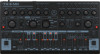
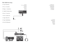
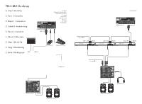
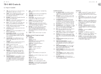
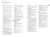
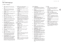
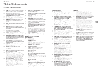
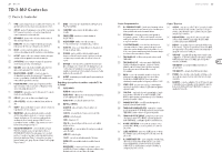
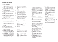
20 TD-3-MO TD-3-MO Controls (EN) Step 2: Controls (1) TUNE - adjust the frequency of the internal VCO oscillator, (17) MODE - select from Track Write, Track Play, Pattern Play, approximately one octave either side of center. Pattern Write. (2) CUTOFF - adjust the cutoff frequency of the low-pass VCF filter. Frequencies above the cutoff will be attenuated, such as the higher-order harmonics. (18) SLIDE TIME - varies the slide time between played notes. (19) SWEEP SPEED - changes the relative speed of ACCENT SWEEP. (3) RESONANCE - adjust the amount of emphasis given to the (20) ACCENT SWEEP - changes the amount of resonance. signal level at the cutoff frequency. 0: no accent sweep,1: high resonance, 2: normal. (4) ENVELOPE - select the depth of modulation applied by the (21) FILTER FM - this varies the amount of frequency envelope generator to the VCF cutoff frequency. modulation of the filter by the audio output. (5) DECAY - controls the amount of time taken for the volume (22) VOLUME - adjust the output level from the rear-panel envelope to decay from the current level to minimum. output and the headphones output. Make sure the volume (6) ACCENT - adjust the amount of accent given to the output is turned down before putting on headphones. for any notes programmed with an accent. (23) MUFFLER - this switch affects the VCA output at higher (7) SOFT ATTACK - varies the envelope generator attack time levels (off and two soft clipping modes). Position 1 for non-accented notes. removes some high frequencies to smooth the sound (8) GATE LED - flashes red to show gating and green is used to when extreme resonance is used. Position 2 removes even more HF content. show if in poly chain mode. (9) DECAY-NORMAL and ACCENT - controls the decay time (24) ACCENT - hold down to force each step to be accented. of the VCF envelope generator for normal and accented notes. The LEDs vary in brightness with the output of the envelope generator. Patchbay (3.5 mm TS input and output connections) (10) FILTER TRACKING - allows the filter frequency to vary with the note being played. Turn CW to let more higher notes through. (11) OVERDRIVE - this increases the amount of VCO signal fed to the filter. At 0%, the normal VCO level is sent. (12) SUB OSC - turn sub oscillator on/off. (13) SUB OSC LEVEL - select sub level low, medium or high. (25) FILTER INPUTS FILTER IN - filter input. FILTER FM IN - the filter can be modulated by the frequency of an external audio signal. FILTER CV IN - controls the filter frequency. (26) INPUTS and OUTPUTS ACCENT IN - a CV input to control Accent (14) TEMPO - adjust the rate at which the pattern and tracks play, from slow to fast. (15) WAVEFORM - select the waveform of the internal VCO oscillator from reverse sawtooth or pulse. When OFF, no square or saw is heard, just the SUB OSC or if resonance is self-oscillating. (Try this with the accent sweep switch in position 1.) (16) TRACK/PATTERN GROUP - select from TRACK 1 to 7 when writing or playing tracks, and PATTERN GROUP I, II, III, IV when writing or playing patterns. Patterns in group I are only available for use in track 1 or 2, patterns in group II for tracks 3 or 4, group III for tracks 5 or 6, and group IV for track 7. SLIDE IN - a CV input to control Slide GATE IN - gate input CV IN - CV input SYNC IN - this input allows the use of an external clock signal. ACCENT OUT - use with the CV and Gate outputs to control another TD-3-MO. GATE OUT - gate output CV OUT - control voltage output of 1V/octave. FILTER OUT - a line-level audio output from the filter. HEADPHONES - connect your headphones to this 3.5 mm TRS output. Make sure the volume is turned down before putting on headphones. Quick Start Guide 21 Sequencer Section (27) D.C./BAR RESET/CLEAR - this is used to clear a pattern from memory, to return a track to the beginning, and to signal that the last pattern is being added to a track. (28) PITCH MODE - selects the pitch mode on or off. The LED will light when in pitch mode. This mode is used to enter the notes when creating patterns. (29) 13-NOTE KEYBOARD - these switches are laid out as a 13-note keyboard, allowing notes to be selected when creating patterns. The lower eight switches are also used when creating, saving, and selecting patterns and tracks. (30) TIME MODE LED - the LED will light when in TIME MODE. (31) TIME MODE ON/OFF - select the TIME MODE on or off. This mode is used when entering the timing (note, tie, or rest) after the notes have been entered in PITCH MODE. (32) BACK - when stepping through a pattern, this allows you to select the last played note, so it can be edited. (33) START / STOP - this allows you to start or stop playing the patterns and tracks. The LED will turn on when playing. (34) FUNCTION - this multipurpose switch is used to return the TD-3-MO to normal mode from PITCH MODE and TIME MODE, and for various operations during pattern and track writing. (35) NORMAL MODE LED - this LED will light when the unit is in normal mode. (36) TRANSPOSE DOWN/NOTE/STEP - this is used to transpose the octave downwards in PITCH MODE, enter a note in TIME MODE, and to enter the number of steps in a pattern. (37) TRANSPOSE UP/TIE/TRIPLET - this is used to transpose the octave upwards in PITCH MODE, enter a tie in TIME MODE, and set the pattern to triplet mode. (38) ACCENT / PATTERN A - this allows an accent to be added to notes in PITCH MODE, and to select "A" patterns such as 1A, 2A, to 8A. (39) SLIDE / PATTERN B - this allows a SLIDE to be added to notes in PITCH MODE, and to select "B" patterns, such as 1B, 2B, to 8B. (40) D.S./WRITE/NEXT/TAP - this allows a pattern to be written to a track, to select the next note in a pattern, and to add manual timing by tapping. Rear Panel (41) OUTPUT - connect this 1/4" TS output to the line-level audio input of your system. Make sure the volume is turned down and the system is turned off before making connections. (42) MIDI OUT/THRU - this 5-pin DIN jack is used to pass MIDI out, and to pass through MIDI data received at the MIDI INPUT. (43) MIDI IN - this 5-pin DIN jack receives MIDI data from an external source. This will commonly be a MIDI keyboard, an external hardware sequencer, a computer equipped with a MIDI interface, etc. (44) USB PORT - this USB type B jack allows connection to a computer. The TD-3-MO will show up as a classcompliant USB MIDI device, capable of supporting MIDI in and out. USB MIDI IN - accepts incoming MIDI data from an application. USB MIDI OUT - sends MIDI data to an application. (45) POWER - turn the synthesizer on or off. Make sure all the connections are made before turning on the unit. (46) DC INPUT - connect the supplied 12V DC power adapter here. The power adapter can be plugged into an AC outlet capable of supplying from 100V to 240V at 50 Hz/60 Hz. Use only the power adapter supplied.
-
 1
1 -
2
-
3
-
4
-
5
-
 6
6 -
 7
7 -
 8
8 -
 9
9 -
 10
10 -
 11
11 -
 12
12 -
 13
13 -
 14
14 -
 15
15 -
 16
16 -
17
-
18
-
19
-
20
-
21
-
22
-
23
-
24
-
25
-
26
-
27
-
28
-
29
-
30
-
31
-
32
-
33
-
34
-
35
-
36
-
37
 |
 |