Brother International CB3-B917 Service Manual - Page 38
After stopping the machine, loosen the screw
 |
View all Brother International CB3-B917 manuals
Add to My Manuals
Save this manual to your list of manuals |
Page 38 highlights
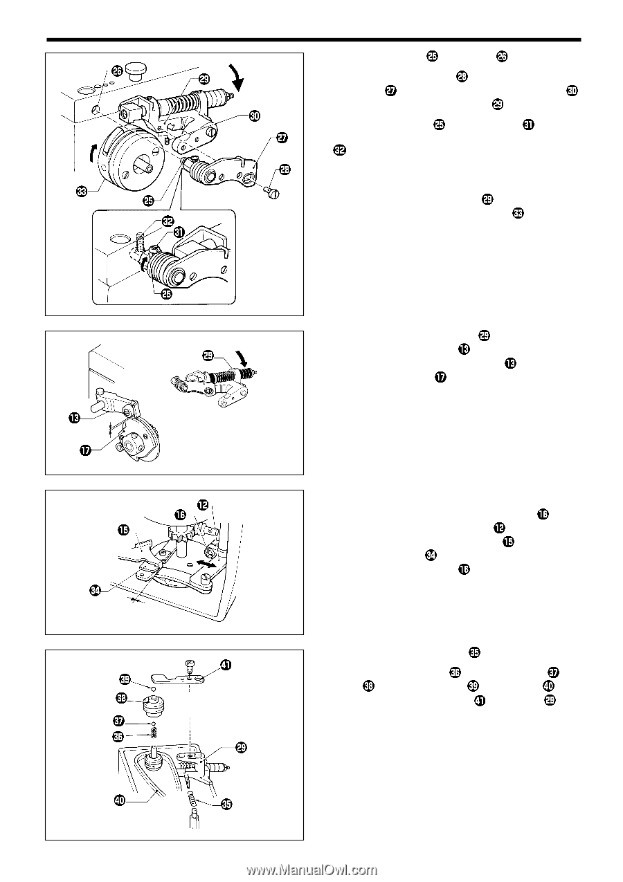
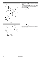
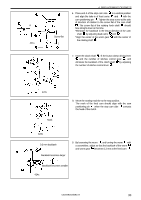
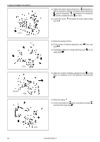
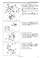
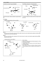
4. REPLACEMENT OF PARTS 18. Insert the brake shaft into the hole in the bed. 19. Insert the brake lever shaft into the oval hole in the brake lever , and provisionally tighten the set screw on the bottom side of the clutch body . 20. Turn the brake shaft until the screw is facing upward, and then secure it by tightening the set screw . * Adjust the brake while referring to section Adjustment of [Brake] (P.39). 21. With the rear part of the clutch pressed, start the sewing machine by rotating the stop cam two or three times. 420s 0.5 mm 425s 0 mm 426s 22. With the rear part of the clutch pressed, adjust the stitch length control lever so that the clearance between the stitch length control lever and the stitch length adjustment cam is 0.5 mm. 23. Tilt the sewing machine downward. 24. After stopping the machine, loosen the screw . Then move the button clamp driving lever to adjust so that the end of the button clamp driving fork and the end of the driving rod claw are aligned. After adjustment is completed, tighten the screw . 25. Attach the clutch tension spring . 26. Fit the pulley return spring , the steel ball 7/32 , the pulley , the steel ball 5/16 and the belt , and then attach the ball presser plate to the clutch . 27. Raise the sewing machine. 28. Attach the needle and installation bolt. 427s CB3-B916A/B917A 32
-
 1
1 -
2
-
3
-
4
-
5
-
6
-
7
-
8
-
9
-
10
-
11
-
12
-
13
-
14
-
15
-
16
-
17
-
18
-
19
-
20
-
21
-
22
-
23
-
24
-
25
-
26
-
27
-
28
-
29
-
30
-
31
-
32
-
 33
33 -
 34
34 -
 35
35 -
 36
36 -
 37
37 -
 38
38 -
 39
39 -
 40
40 -
 41
41 -
 42
42 -
 43
43 -
44
-
45
-
46
-
47
-
48
-
49
-
50
-
51
-
52
-
53
-
54
-
55
-
56
 |
 |