Brother International CB3-B917 Service Manual - Page 40
Operating lever pawl
 |
View all Brother International CB3-B917 manuals
Add to My Manuals
Save this manual to your list of manuals |
Page 40 highlights
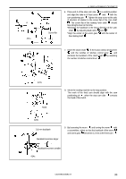
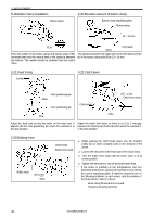
4-3.Operating lever pawl < Disassembly > 1.Bolt 4. REPLACEMENT OF PARTS < Assembly > 428s 2.Open the cover and tilt the sewing machine downward. 3.Put the machine into the start condition. 436s 4.Operating lever pawl 0.6 mm 1. Attach the operating lever pawl to the connecting rod assembly . With the sewing machine in the start condition, install so that there is a clearance of 0.5 mm for the operating lever pawl and the button clamp operating fork . 2. Raise the sewing machine. 3. Attach the bolt. 437s CB3-B916A/B917A 34
-
 1
1 -
2
-
3
-
4
-
5
-
6
-
7
-
8
-
9
-
10
-
11
-
12
-
13
-
14
-
15
-
16
-
17
-
18
-
19
-
20
-
21
-
22
-
23
-
24
-
25
-
26
-
27
-
28
-
29
-
30
-
31
-
32
-
33
-
34
-
 35
35 -
 36
36 -
 37
37 -
 38
38 -
 39
39 -
 40
40 -
 41
41 -
 42
42 -
 43
43 -
 44
44 -
 45
45 -
46
-
47
-
48
-
49
-
50
-
51
-
52
-
53
-
54
-
55
-
56
 |
 |
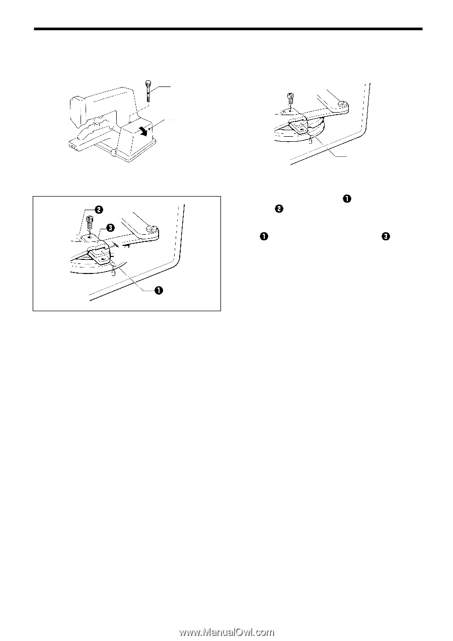
4. REPLACEMENT OF PARTS
CB3-B916A/B917A
34
4-3.Operating lever pawl
< Disassembly >
< Assembly >
1.Bolt
2.Open the cover
and tilt the sewing
machine downward.
3.Put the machine into
the start condition.
428s
4.Operating lever pawl
436s
1.
Attach the operating lever pawl
to the connecting rod
assembly
.
With the sewing machine in the start condition, install so
that there is a clearance of 0.5 mm for the operating lever
pawl
and the button clamp operating fork
.
2.
Raise the sewing machine.
3.
Attach the bolt.
437s
0.6 mm