Brother International CB3-B917 Service Manual - Page 42
Movable knife, 8.Number of stitches control lever, 9.Number of stitches adjustment cam, 10.Pawl
 |
View all Brother International CB3-B917 manuals
Add to My Manuals
Save this manual to your list of manuals |
Page 42 highlights
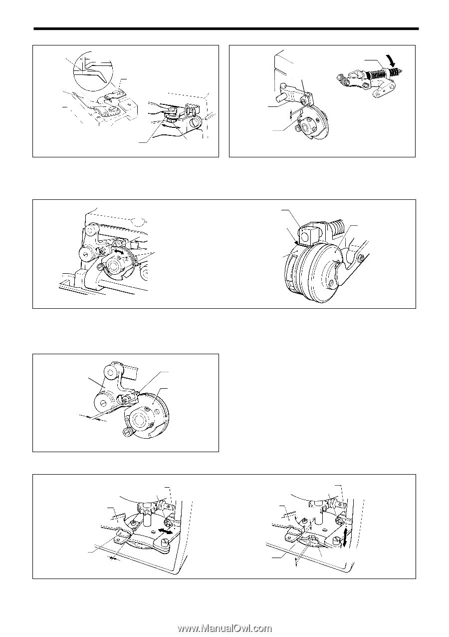
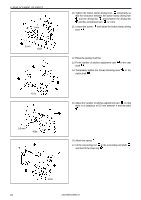
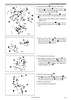
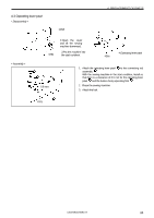
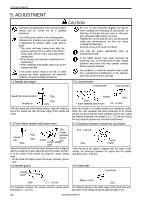
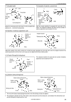
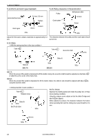
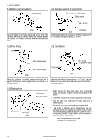
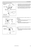
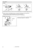
5-7.Movable knife 5. ADJUSTMENT 5-8.Number of stitches control lever A 0.5 - 1 mm Connecting rod Movable knife 335s Fixed knife Connecting lever 336s Nut Roller Number of stitches adjustment lever 0.5 mm Number of stitches adjustment cam Clutch 425s Adjust the connecting rod so the boss A on the movable knife extends 0.5 - 1 mm from the fixed knife. 5-9.Number of stitches adjustment cam Start the sewing machine by pressing the rear part of the clutch. The clearance between the pawl and the number of stitches adjustment cam should be 0.5 mm. Number of stitches adjustment cam Screw Stopper bracket Reference line Stop cam Pulley 502s 503s Adjust the position of the stitch control cam so that the pulley separates from the stop cam when the stopper bracket of the clutch body and the reference line on the stop cam are aligned at the final needle position. 5-10.Pawl of thread trimming lever Thread trimming lever 0.5 mm 312s Pawl Number of stitches adjustment cam The clearance between the pawl and the number of stitches adjustment cam should be 0.5 mm. 5-11.Button clamp driving lever Button clamp driving lever Button clamp Screw driving fork Button clamp driving lever Button clamp Screw driving fork 1 mm Driving rod claw 0 mm 426s Driving link 1 mm Vertical feed cam 416s 1. The end of the button clamp driving fork and the end of the driving rod claw are aligned. 2. The clearances between the tip of the button clamp driving fork and the driving link, and between the vertical feed cam and the driving link, should each be 1 mm. CB3-B916A/B917A 36
-
 1
1 -
2
-
3
-
4
-
5
-
6
-
7
-
8
-
9
-
10
-
11
-
12
-
13
-
14
-
15
-
16
-
17
-
18
-
19
-
20
-
21
-
22
-
23
-
24
-
25
-
26
-
27
-
28
-
29
-
30
-
31
-
32
-
33
-
34
-
35
-
36
-
 37
37 -
 38
38 -
 39
39 -
 40
40 -
 41
41 -
 42
42 -
 43
43 -
 44
44 -
 45
45 -
 46
46 -
 47
47 -
48
-
49
-
50
-
51
-
52
-
53
-
54
-
55
-
56
 |
 |