Brother International CB3-B917 Service Manual - Page 43
Worm and worm gear backlash, 13.Pulley clearance in thrust direction, 14.Slider, B917A, B916A
 |
View all Brother International CB3-B917 manuals
Add to My Manuals
Save this manual to your list of manuals |
Page 43 highlights
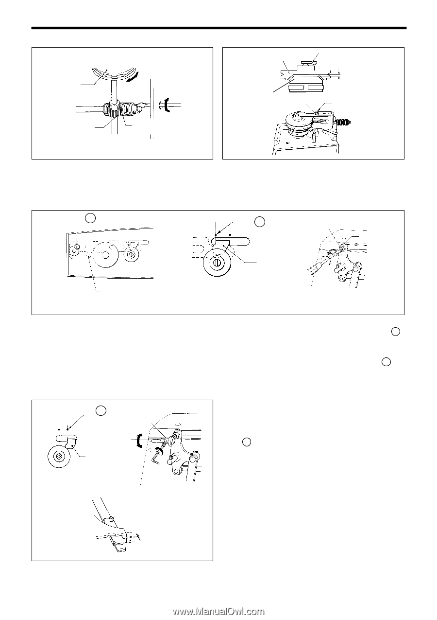
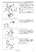
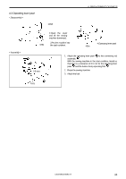
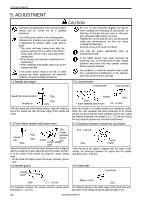
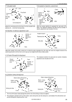
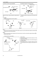
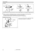
5. ADJUSTMENT 5-12.Worm and worm gear backlash Horizontal feed cam Worm gear Approx. 0.3 mm Tighten Worm Loosen 5-13.Pulley clearance in thrust direction Pulley Ball presser plate 0.8 mm Clutch plate Nut Screw 424s 346s Adjust the feed cam to obtain a backlash of approximately 0.3 The clearance between the pulley and the clutch plate should mm. be 0.8 mm. 5-14.Slider < With the sewing machine in the stop condition > Take-in B Take-in A Eccentric shaft Set screw Slider B 349s Slider B 350s 351s B917A B916A B917A When the presser lifter pedal is depressed to lift the button clamp, the eccentric shaft should be adjusted so that take-in B of slider B is at the center of the frame hole. B916A When the presser lifter pedal is depressed to lift the button clamp, the slider B side should be aligned with take-in A by using the eccentric shaft. < Sewing machine in start condition > Take-in C Stopper screw Slider B 504s B917A /B 916A 505s B917A / B916A Depress the starting pedal and rotate the pulley two or three times (starting condition). Using the stopper screw, adjust so that the slider B edge and take-in C are aligned. When adjusted as above, the clearance between the button clamp operating fork and the driving lever pawl should be 0.6 mm. 506s 0.6 mm 37 CB3-B916A/B917A
-
 1
1 -
2
-
3
-
4
-
5
-
6
-
7
-
8
-
9
-
10
-
11
-
12
-
13
-
14
-
15
-
16
-
17
-
18
-
19
-
20
-
21
-
22
-
23
-
24
-
25
-
26
-
27
-
28
-
29
-
30
-
31
-
32
-
33
-
34
-
35
-
36
-
37
-
 38
38 -
 39
39 -
 40
40 -
 41
41 -
 42
42 -
 43
43 -
 44
44 -
 45
45 -
 46
46 -
 47
47 -
 48
48 -
49
-
50
-
51
-
52
-
53
-
54
-
55
-
56
 |
 |