Brother International HL 760 Service Manual - Page 10
NC.
 |
UPC - 012502562832
View all Brother International HL 760 manuals
Add to My Manuals
Save this manual to your list of manuals |
Page 10 highlights
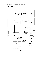
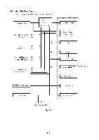
CHAPTER II THEORY OF OPERATION 1. ELECTRONICS 1.1 General Block Diagram Fig. 2.1 shows a general block diagram of this printer. External device e N e Optional RAM (SIMM) (max. 32Mbytes) Optional I/F board (Mac. RS-232C) Control system 1 External device ell III.N . ir) O 0 0- 0 0 .0 CO >, Expansion memory I/O N Video control block Expansion I/O r IInterface block V' 0- Z 0- ? (1) _O i ''' 11. 1.1 Engine control block e Operation block (Operation panel) L Erase lamp r [ Laser scanner unit I II Drive block (Stepping motor) L. , / .... .. .,, Paper tray unit Paper tray e / Drum unit e N Transfer block • / Manual feed / / N Developing block i Drum C.Charging block } ( Cleaner block Toner cartridge F unit e Paper eject block •. L Paper feed system ., Image generation system L J Fig. 2.1
-
 1
1 -
2
-
3
-
4
-
 5
5 -
 6
6 -
 7
7 -
 8
8 -
 9
9 -
 10
10 -
 11
11 -
 12
12 -
 13
13 -
 14
14 -
 15
15 -
16
-
17
-
18
-
19
-
20
-
21
-
22
-
23
-
24
-
25
-
26
-
27
-
28
-
29
-
30
-
31
-
32
-
33
-
34
-
35
-
36
-
37
-
38
-
39
-
40
-
41
-
42
-
43
-
44
 |
 |
