Brother International HL 760 Service Manual - Page 30
connectors
 |
UPC - 012502562832
View all Brother International HL 760 manuals
Add to My Manuals
Save this manual to your list of manuals |
Page 30 highlights
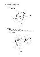
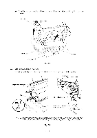
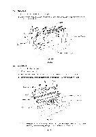
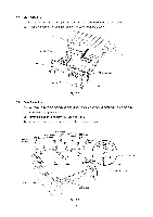
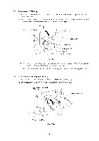
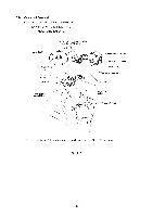
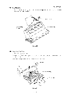
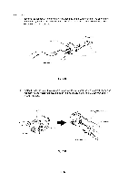
3.10 High-voltage Power Supply PCB Assy (1) Remove the screw securing the high-voltage power supply PCB assy. (2) Disconnect the four connectors from the PCB. Insulation sheet High-voltage power supply PCB assy Drum ground PCB harness (P4) GI Fan motor harness (P2) 7 Erase lamp harness (P3) /is Density volume HV Flat cable (P1) Density dial Fig. 3.11 NOTE: When reassembling, the density volume must be fitted into the cut side of the density dial. 3.11 Fan Motor (1) Disconnect the connector from the high-voltage power supply PCB. ( It has been disconnected already. See above) (2) Take off the fan motor assy. Fan motor assy Fig. 3.12 III - 8
-
 1
1 -
2
-
3
-
4
-
5
-
6
-
7
-
8
-
9
-
10
-
11
-
12
-
13
-
14
-
15
-
16
-
17
-
18
-
19
-
20
-
21
-
22
-
23
-
24
-
 25
25 -
 26
26 -
 27
27 -
 28
28 -
 29
29 -
 30
30 -
 31
31 -
 32
32 -
 33
33 -
 34
34 -
 35
35 -
36
-
37
-
38
-
39
-
40
-
41
-
42
-
43
-
44
 |
 |

3.10
High
-voltage
Power
Supply
PCB
Assy
(1)
Remove
the
screw
securing
the
high
-voltage
power
supply
PCB
assy.
(2)
Disconnect
the
four
connectors
from
the
PCB.
Insulation
sheet
High
-voltage
power
supply
PCB
assy
Drum
ground
PCB
harness
(P4)
GI
Fan
motor
harness
(P2)
Erase
lamp
harness
(P3)
HV
Flat
cable
(P1)
7
Density
dial
Fig.
3.11
/is
Density
volume
NOTE:
When
reassembling,
the
density
volume
must
be
fitted
into
the
cut
side
of
the
density
dial.
3.11
Fan
Motor
(1)
Disconnect
the
connector
from
the
high
-voltage
power
supply
PCB.
(
It
has
been
discon-
nected
already.
See
above)
(2)
Take
off
the
fan
motor
assy.
Fan
motor
assy
Fig.
3.12
III
-
8