Brother International HL 760 Service Manual - Page 4
Contents
 |
UPC - 012502562832
View all Brother International HL 760 manuals
Add to My Manuals
Save this manual to your list of manuals |
Page 4 highlights
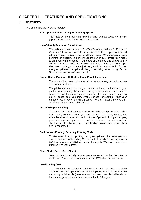
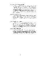
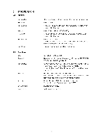
CONTENTS CHAPTER I FEATURES AND SPECIFICATIONS 1. FEATURES 2. SPECIFICATIONS 2.1 Printing 2.2 Functions 2.3 Electrical and Mechanical 2.4 Paper Specification 2.5 Print Delivery 2.6 Paper 2.7 Effective Printing Area 3. SAFETY INFORMATION 3.1 Laser Safety (110 - 120V Model only)) 3.2 CDRH Regulations (110 -120V Model only) 3.3 Caution for Laser Product CHAPTER II THEORY OF OPERATION 1. ELECTRONICS 1.1 General Block Diagram 1.2 Main PCB Block Diagram 1.3 Main PCB 1.3.1 CPU Core 1.3.2 ASIC 1.3.3 ROM 1.3.4 DRAM 1.3.5 Optional RAM 1.3.6 Optional Serial I/O 1.3.7 EEPROM 1.3.8 Reset Circuit 1.3.9 CDCC I/O 1.3.10 Engine I/O 1.3.11 Paper Feed Motor Drive Circuit 1.4 Panel Sensor PCB 1.5 Power Supply 2. MECHANICS 2.1 Overview of printing mechanism 2.2 Paper Transfer 2.2.1 2.2.2 2.2.3 Paper Supply Paper Registration Paper Eject 2.3 Sensors 2.3.1 Cover Sensor 2.3.2 Toner Empty Sensor 2.4 Drum Unit 2.4.1 2.4.2 2.4.3 2.4.4 Photosensitive Drum Primary Charger Developer Roller Transfer Roller I-1 1-1 1-3 1-3 1-3 . 1-4 Refer to HL-730 (P. 1-7) Refer to HL-730 (P.1-7) Refer to HL-730 (P.I-7) Refer to HL-730 (P. 1-8) Refer to HL-730 (P.I-10) Refer to HL-730 (P.1-10) Refer to HL-730 (P1-10) Refer to HL-730 (P I-11) II-1 11-1 11-1 11-2 11-3 11-3 11-4 11-7 11-8 11-9 II-10 11-10 11-11 11-11 11-12 11-13 Refer to HL-730 (P. 11-22) Refer to HL-730 (P11-23) Refer to HL-730 (P.I1-24) Refer to HL-730 (P. 11-24) Refer to HL-730 (P. 11-25) Refer to HL-730 (P11-25) Refer to HL-730 (P. 11-25) Refer to HL-730 (P. 11-26) Refer to HL-730 (P. 11-27) Refer to HL-730 (P. 11-27) Refer to HL-730 (P11-27) Refer to HL-730 (P. 11-28) Refer to HL-730 (P11-28) Refer to HL-730 (P. 11-28) Refer to HL-730 (P. 11-28) Refer to HL-730 (P 11-28)
-
 1
1 -
 2
2 -
 3
3 -
 4
4 -
 5
5 -
 6
6 -
 7
7 -
 8
8 -
 9
9 -
 10
10 -
11
-
12
-
13
-
14
-
15
-
16
-
17
-
18
-
19
-
20
-
21
-
22
-
23
-
24
-
25
-
26
-
27
-
28
-
29
-
30
-
31
-
32
-
33
-
34
-
35
-
36
-
37
-
38
-
39
-
40
-
41
-
42
-
43
-
44
 |
 |
