Brother International HL 760 Service Manual - Page 31
Drive, Remove, screws, securing, drive, unit., Motor, motor, assy., sink.
 |
UPC - 012502562832
View all Brother International HL 760 manuals
Add to My Manuals
Save this manual to your list of manuals |
Page 31 highlights
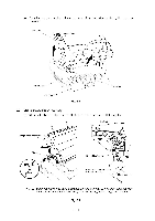
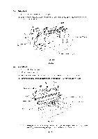
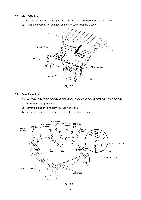
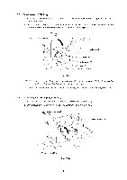
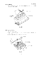
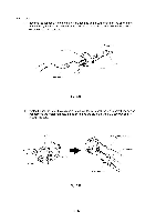
3.12 Drive Unit (1) Remove the four screws securing the drive unit. Drive unit Fig. 3.13 3.13 Main Motor Assy and Motor Heat Sink (1) Remove the two screws securing the main motor assy. (2) Remove the two screws securing the motor heat sink. Motor heat sink 99 9 9 0 O Main motor assy
-
 1
1 -
2
-
3
-
4
-
5
-
6
-
7
-
8
-
9
-
10
-
11
-
12
-
13
-
14
-
15
-
16
-
17
-
18
-
19
-
20
-
21
-
22
-
23
-
24
-
25
-
 26
26 -
 27
27 -
 28
28 -
 29
29 -
 30
30 -
 31
31 -
 32
32 -
 33
33 -
 34
34 -
 35
35 -
 36
36 -
37
-
38
-
39
-
40
-
41
-
42
-
43
-
44
 |
 |

3.12
Drive
Unit
(1)
Remove
the
four
screws
securing
the
drive
unit.
Drive
unit
Fig.
3.13
3.13
Main
Motor
Assy
and
Motor
Heat
Sink
(1)
Remove
the
two
screws
securing
the
main
motor
assy.
(2)
Remove
the
two
screws
securing
the
motor
heat
sink.
Motor
heat
sink
99
0
Main
motor
assy
9
9
O