Brother International HL 760 Service Manual - Page 27
disassembling
 |
UPC - 012502562832
View all Brother International HL 760 manuals
Add to My Manuals
Save this manual to your list of manuals |
Page 27 highlights
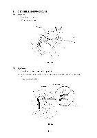
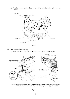
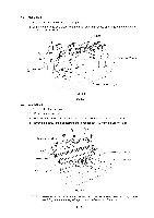
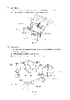
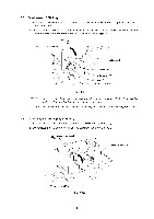
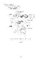
3.4 Fixing Unit (1) Remove the screw securing the fixing unit. (2) Lifting up the fixing unit, disconnect the two heater harnesses and remove the conector of thermistor on EL PCB. Fixing unit I U i 1Di11) Heater harness _J1 (Blue) Heater harness (Brown) Thermistor harness (White) EL PCB Fig. 3.5 3.5 Scanner Unit (1) Remove the three screws. (2) Lift out the scanner unit. (3) Disconnect the three connectors of the scanner unit from the panel sensor PCB. (4) Remove the screw and disassemble the Toner sensor PCB from the Scanner unit. Mirror Toner sensor PCB Scanner unit S Seal sponge 1 Connectors ( P2, P3, P9) ch11 Panel sensor PCB Fig. 3.6 NOTE: Never touch the inside of the scanner unit or the mirror when disassembling or reassembling. If there is any garbage or dust on the mirror; blow it off III - 5
-
 1
1 -
2
-
3
-
4
-
5
-
6
-
7
-
8
-
9
-
10
-
11
-
12
-
13
-
14
-
15
-
16
-
17
-
18
-
19
-
20
-
21
-
 22
22 -
 23
23 -
 24
24 -
 25
25 -
 26
26 -
 27
27 -
 28
28 -
 29
29 -
 30
30 -
 31
31 -
 32
32 -
33
-
34
-
35
-
36
-
37
-
38
-
39
-
40
-
41
-
42
-
43
-
44
 |
 |
