Brother International HL 760 Service Manual - Page 28
upside-down
 |
UPC - 012502562832
View all Brother International HL 760 manuals
Add to My Manuals
Save this manual to your list of manuals |
Page 28 highlights
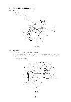
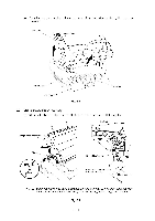
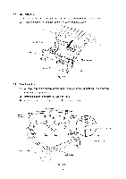
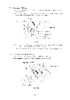
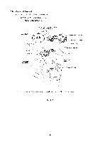
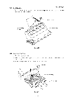
3.6 Main PCB Assy (1) Remove four screws securing the main PCB holder on the back side of the printer. (2) Grasp the hooks at left and right and draw out the main PCB assy. Rail Main PCB assy Hook , / I / F Shield assy Screws Fig. 3.7 Hook 3.7 Base Plate Assy NOTE: Prior to turning the printer upside-down, drum unit should be removed from the printer (1) Turn the printer upside down. (2) Remove the six M4 and eight M3 tapping screws. (3) Lift out the base plate assy and remove the grounding screw. M4 Screws (B tight) M3 Screws M4 Screws (S tight) M4 Screws (B tight) M3 Screws (B tight) (S tight) M3 Screws (S tight) M4 Screws (B tight) ...------nk - N C) cle15= \\ fd. Grounding wire Washer Grounding screw Base plate assy Rubber foot Fig. 3.8 III - 6
-
 1
1 -
2
-
3
-
4
-
5
-
6
-
7
-
8
-
9
-
10
-
11
-
12
-
13
-
14
-
15
-
16
-
17
-
18
-
19
-
20
-
21
-
22
-
 23
23 -
 24
24 -
 25
25 -
 26
26 -
 27
27 -
 28
28 -
 29
29 -
 30
30 -
 31
31 -
 32
32 -
 33
33 -
34
-
35
-
36
-
37
-
38
-
39
-
40
-
41
-
42
-
43
-
44
 |
 |
