Brother International PR-600 Users Manual - English - Page 188
Preparing to use the cap, frame - cap driver
 |
View all Brother International PR-600 manuals
Add to My Manuals
Save this manual to your list of manuals |
Page 188 highlights
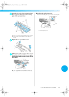
Sapphire.book Page 170 Friday, August 1, 2003 9:12 AM Appendix Preparing to use the cap frame ■ Installing the cap frame driver Press → → →→ Pass the machine bed through the ring of the 3 cap frame driver. in order to view a video of the operation on the LCD (see page 151). Remove the embroidery frame holder from the carriage on the machine, and then install the cap frame driver. Before removing the embroidery frame holder, remove the embroidery frame. (Refer to "Removing the embroidery frame" on page 45.) Loosen and then remove the two thumb 1 screws and the embroidery frame holder. 1 1 1 Machine bed Note ● Be careful that the cap frame driver does not hit any nearby parts, such as the presser foot. Attach the cap frame driver to the carriage as described below in steps 4 through 6. Insert the two thumb screws at the bottom of 4 the cap frame driver into the v-cuts in the carriage, and then place the mounting plate of the cap frame driver on top of the framemounting plate of the carriage. 1 Thumb screws • The removed thumb screws remain attached to the embroidery frame holder. 1 3 4 1 Put two thumb screws not to lose Remove the two upper thumb screws of the 2 cap frame driver, and then loosen the two lower thumb screws (4 turns). 1 2 1 1 Notch in the carriage 2 Thumb screw of the cap frame driver 3 Mounting plate of the cap frame driver 4 Frame-mounting plate of the carriage 2 1 Upper thumb screws 2 Lower thumb screws 170
-
 1
1 -
2
-
3
-
4
-
5
-
6
-
7
-
8
-
9
-
10
-
11
-
12
-
13
-
14
-
15
-
16
-
17
-
18
-
19
-
20
-
21
-
22
-
23
-
24
-
25
-
26
-
27
-
28
-
29
-
30
-
31
-
32
-
33
-
34
-
35
-
36
-
37
-
38
-
39
-
40
-
41
-
42
-
43
-
44
-
45
-
46
-
47
-
48
-
49
-
50
-
51
-
52
-
53
-
54
-
55
-
56
-
57
-
58
-
59
-
60
-
61
-
62
-
63
-
64
-
65
-
66
-
67
-
68
-
69
-
70
-
71
-
72
-
73
-
74
-
75
-
76
-
77
-
78
-
79
-
80
-
81
-
82
-
83
-
84
-
85
-
86
-
87
-
88
-
89
-
90
-
91
-
92
-
93
-
94
-
95
-
96
-
97
-
98
-
99
-
100
-
101
-
102
-
103
-
104
-
105
-
106
-
107
-
108
-
109
-
110
-
111
-
112
-
113
-
114
-
115
-
116
-
117
-
118
-
119
-
120
-
121
-
122
-
123
-
124
-
125
-
126
-
127
-
128
-
129
-
130
-
131
-
132
-
133
-
134
-
135
-
136
-
137
-
138
-
139
-
140
-
141
-
142
-
143
-
144
-
145
-
146
-
147
-
148
-
149
-
150
-
151
-
152
-
153
-
154
-
155
-
156
-
157
-
158
-
159
-
160
-
161
-
162
-
163
-
164
-
165
-
166
-
167
-
168
-
169
-
170
-
171
-
172
-
173
-
174
-
175
-
176
-
177
-
178
-
179
-
180
-
181
-
182
-
 183
183 -
 184
184 -
 185
185 -
 186
186 -
 187
187 -
 188
188 -
 189
189 -
 190
190 -
 191
191 -
 192
192 -
 193
193 -
194
-
195
-
196
-
197
-
198
-
199
-
200
-
201
-
202
-
203
-
204
-
205
-
206
-
207
-
208
-
209
-
210
-
211
-
212
-
213
-
214
-
215
-
216
-
217
-
218
-
219
-
220
-
221
-
222
-
223
-
224
-
225
-
226
-
227
 |
 |
