Canon MF4690 Service Manual - Page 104
Removing the High Voltage Power Supply Board
 |
UPC - 013803076820
View all Canon MF4690 manuals
Add to My Manuals
Save this manual to your list of manuals |
Page 104 highlights
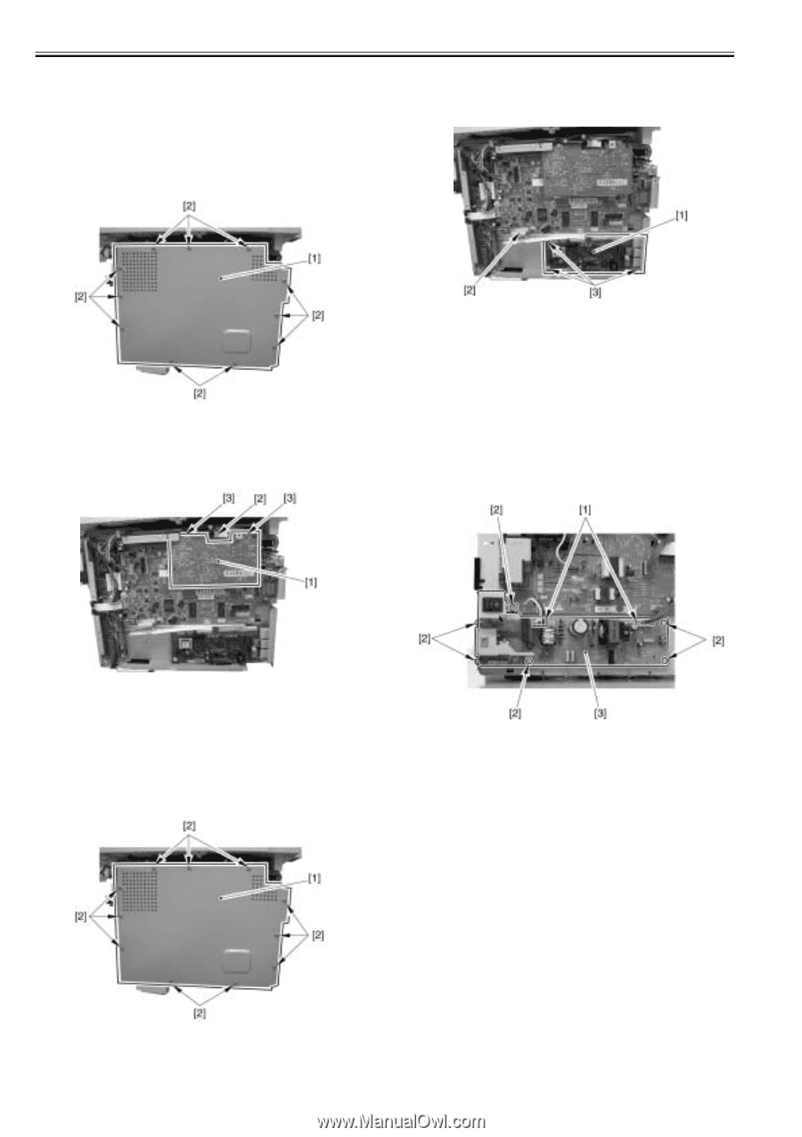
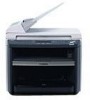
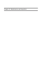
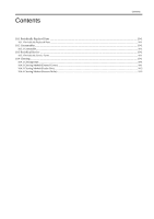
Chapter 9 9.3.10 Analog Processor PCB 9.3.11.2 Removing the NCU Board 0016-5016 9.3.10.1 Preparation for Removing the Analog processor 1) Remove the NCU board [1]. - 1 connector [2] PCB - 3 screws [3] 0016-5021 1) Remove the front cover. 2) Remove the right cover. 3) Remove the left cover. 4) Remove the rear cover. 5) Remove the frame [1]. - 11 screws [2] F-9-28 9.3.10.2 Removing the Analog processor PCB 1) Remove the Analog processor PCB [1]. - 1 connector [2] - 2 screws [3] F-9-31 9.3.12 Power Supply PCB 9.3.12.1 Preparation for Removing the Power Supply Board 0016-5017 1) Remove the front cover. 2) Remove the right cover. 3) Remove the left cover. 4) Remove the rear cover. 0016-5022 9.3.12.2 Removing the Power Supply Board 0016-5018 1) Remove the power supply board [3]. - 2 connectors [1] - 6 screws [2] 9.3.11 NCU Board F-9-29 9.3.11.1 Preparation for Removing the NCU Board 0016-5015 1) Remove the front cover. 2) Remove the right cover. 3) Remove the left cover. 4) Remove the rear cover. 5) Remove the frame [1]. - 11 screws [2] F-9-32 9.3.13 High-voitage Power Supply PCB 9.3.13.1 Preparation for Removing the High Voltage Power Supply Board 0016-5019 1) Remove the front cover. 2) Remove the right cover. 3) Remove the left cover. 4) Remove the rear cover. 5) Remove the control panel. 6) Remove the printer cover. 7) Remove the upper cover. 9.3.13.2 Removing the High Voltage Power Supply Board 0016-5020 1) Unhook the 2 claws [1], and remove the fixing guide [2]. F-9-30 9-6
-
 1
1 -
2
-
3
-
4
-
5
-
6
-
7
-
8
-
9
-
10
-
11
-
12
-
13
-
14
-
15
-
16
-
17
-
18
-
19
-
20
-
21
-
22
-
23
-
24
-
25
-
26
-
27
-
28
-
29
-
30
-
31
-
32
-
33
-
34
-
35
-
36
-
37
-
38
-
39
-
40
-
41
-
42
-
43
-
44
-
45
-
46
-
47
-
48
-
49
-
50
-
51
-
52
-
53
-
54
-
55
-
56
-
57
-
58
-
59
-
60
-
61
-
62
-
63
-
64
-
65
-
66
-
67
-
68
-
69
-
70
-
71
-
72
-
73
-
74
-
75
-
76
-
77
-
78
-
79
-
80
-
81
-
82
-
83
-
84
-
85
-
86
-
87
-
88
-
89
-
90
-
91
-
92
-
93
-
94
-
95
-
96
-
97
-
98
-
 99
99 -
 100
100 -
 101
101 -
 102
102 -
 103
103 -
 104
104 -
 105
105 -
 106
106 -
 107
107 -
 108
108 -
 109
109 -
110
-
111
-
112
-
113
-
114
-
115
-
116
-
117
-
118
-
119
-
120
-
121
-
122
-
123
-
124
-
125
-
126
-
127
-
128
-
129
-
130
-
131
-
132
-
133
-
134
-
135
-
136
-
137
-
138
-
139
-
140
-
141
-
142
-
143
-
144
-
145
-
146
-
147
-
148
-
149
-
150
-
151
-
152
-
153
-
154
-
155
-
156
-
157
-
158
-
159
-
160
-
161
-
162
-
163
-
164
-
165
-
166
-
167
-
168
-
169
-
170
-
171
-
172
-
173
-
174
-
175
-
176
-
177
-
178
-
179
-
180
-
181
-
182
 |
 |