Canon MF4690 Service Manual - Page 46
Contact Sensor, 3.3.1 Removing the Contact Sensor
 |
UPC - 013803076820
View all Canon MF4690 manuals
Add to My Manuals
Save this manual to your list of manuals |
Page 46 highlights
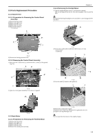
Chapter 3 Be sure not to get the bottom surface of the scanner glass soiled. F-3-10 7) Unhook the 1 claw [1], and remove the gear [3] with the belt [2]. F-3-14 4) Remove the 2 spacers [1]. 5) Remove the contact sensor unit [2] upward. F-3-11 8) Remove the 3 screws [1] to remove the shaft retainer [2], the grounding plate [3] and the motor unit [4]. F-3-15 Points to Note at Attaching Be sure to fit the gear [1] of the belt with the gear [2] on the bottom surface of the contact sensor unit. F-3-12 9) Remove the 2 screws [1] to remove the flat bed motor [2]. 3.3.3 Contact Sensor F-3-13 3.3.3.1 Removing the Contact Sensor 0016-5034 1) Open the copyboard glass cover [1] and detach it upward. Pull out the hinge [2] on the left side while tilting it toward the rear side. Be sure to put the copyboard glass cover that you detached onto the mount etc., so as not to damage the cable. 2) Remove the 4 screws [3], and detach the copyboard glass cover [4]. 3) Remove the copyboard glass cover [5]. 3-6 F-3-16 6) Disconnect the connector [1]. F-3-17
-
 1
1 -
2
-
3
-
4
-
5
-
6
-
7
-
8
-
9
-
10
-
11
-
12
-
13
-
14
-
15
-
16
-
17
-
18
-
19
-
20
-
21
-
22
-
23
-
24
-
25
-
26
-
27
-
28
-
29
-
30
-
31
-
32
-
33
-
34
-
35
-
36
-
37
-
38
-
39
-
40
-
 41
41 -
 42
42 -
 43
43 -
 44
44 -
 45
45 -
 46
46 -
 47
47 -
 48
48 -
 49
49 -
 50
50 -
 51
51 -
52
-
53
-
54
-
55
-
56
-
57
-
58
-
59
-
60
-
61
-
62
-
63
-
64
-
65
-
66
-
67
-
68
-
69
-
70
-
71
-
72
-
73
-
74
-
75
-
76
-
77
-
78
-
79
-
80
-
81
-
82
-
83
-
84
-
85
-
86
-
87
-
88
-
89
-
90
-
91
-
92
-
93
-
94
-
95
-
96
-
97
-
98
-
99
-
100
-
101
-
102
-
103
-
104
-
105
-
106
-
107
-
108
-
109
-
110
-
111
-
112
-
113
-
114
-
115
-
116
-
117
-
118
-
119
-
120
-
121
-
122
-
123
-
124
-
125
-
126
-
127
-
128
-
129
-
130
-
131
-
132
-
133
-
134
-
135
-
136
-
137
-
138
-
139
-
140
-
141
-
142
-
143
-
144
-
145
-
146
-
147
-
148
-
149
-
150
-
151
-
152
-
153
-
154
-
155
-
156
-
157
-
158
-
159
-
160
-
161
-
162
-
163
-
164
-
165
-
166
-
167
-
168
-
169
-
170
-
171
-
172
-
173
-
174
-
175
-
176
-
177
-
178
-
179
-
180
-
181
-
182
 |
 |
