Canon MF4690 Service Manual - Page 35
Function Configuration, 2.1 Basic Operation Sequence - laser printer
 |
UPC - 013803076820
View all Canon MF4690 manuals
Add to My Manuals
Save this manual to your list of manuals |
Page 35 highlights
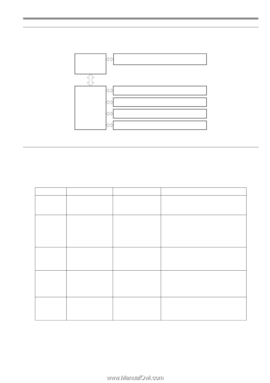
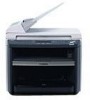
2.1 Construction Chapter 2 2.1.1 Function Configuration 0016-1809 The functions of this host machine are mainly composed of the 7 blocks: System Control System, Scanning Control System, Printer Control System, Laser Scanner System, Image Formation System, Fixing System, Pickup/Feeding System. Below is the block diagram. System Control System Scanning Control System Laser / Scanner System Printer Control System Image Formation System Fixing System Pickup / Feeding System F-2-1 2.2 Basic Sequence 2.2.1 Basic Operation Sequence 0016-1810 The operations of this host machine are controlled by CPUs of the SCNT board within the Reader Controller System and the DCNT board within the Engine Control System. The table below shows the purpose of each interval and the outline of the operations of reader unit and the engine from turnon of the power supply to stop of each motor after printing. interval name WAIT (wait) STBY (standby) definition of interval purpose T-2-1 remarks Interval between turnon of the power supply and the end of the initial drive To clear the drum surface potential Presence/absence of cartridge is detected during this interval. and to execute the cleaning of transfer charging roller Interval between the end of WAIT To make the host machine ready for or LSTR and input of print printing command from SCNT board, or interval between the end of LSTR and turnoff of power supply INTR (initial rotation) Interval between the input of print command from SCNT and turnon of the pickup solenoid To stabilize the photosensitive drum as a preparation for printing Also to clean the transfer charging roller PRINT (print) Interval between the end of initial To form an image onto the rotation and turnoff of the primary photosensitive drum based on the high-voltage output video signal input from the SCNT board and to transfer the toner image onto media LSTR (last rotation) Interval between turnoff of the primary high-voltage output and stop of the main motor To fully deliver the final sheet printed Also to clean the transfer charging roller On input of print command from the SCNT board, host machine enters INTR immediately after LSTR. However, depending on the conditions shown below, the host machine may not start INTR immediately. -media size -temperature of the fixing assembly 2-1
-
 1
1 -
2
-
3
-
4
-
5
-
6
-
7
-
8
-
9
-
10
-
11
-
12
-
13
-
14
-
15
-
16
-
17
-
18
-
19
-
20
-
21
-
22
-
23
-
24
-
25
-
26
-
27
-
28
-
29
-
 30
30 -
 31
31 -
 32
32 -
 33
33 -
 34
34 -
 35
35 -
 36
36 -
 37
37 -
 38
38 -
 39
39 -
 40
40 -
41
-
42
-
43
-
44
-
45
-
46
-
47
-
48
-
49
-
50
-
51
-
52
-
53
-
54
-
55
-
56
-
57
-
58
-
59
-
60
-
61
-
62
-
63
-
64
-
65
-
66
-
67
-
68
-
69
-
70
-
71
-
72
-
73
-
74
-
75
-
76
-
77
-
78
-
79
-
80
-
81
-
82
-
83
-
84
-
85
-
86
-
87
-
88
-
89
-
90
-
91
-
92
-
93
-
94
-
95
-
96
-
97
-
98
-
99
-
100
-
101
-
102
-
103
-
104
-
105
-
106
-
107
-
108
-
109
-
110
-
111
-
112
-
113
-
114
-
115
-
116
-
117
-
118
-
119
-
120
-
121
-
122
-
123
-
124
-
125
-
126
-
127
-
128
-
129
-
130
-
131
-
132
-
133
-
134
-
135
-
136
-
137
-
138
-
139
-
140
-
141
-
142
-
143
-
144
-
145
-
146
-
147
-
148
-
149
-
150
-
151
-
152
-
153
-
154
-
155
-
156
-
157
-
158
-
159
-
160
-
161
-
162
-
163
-
164
-
165
-
166
-
167
-
168
-
169
-
170
-
171
-
172
-
173
-
174
-
175
-
176
-
177
-
178
-
179
-
180
-
181
-
182
 |
 |