Canon MF4690 Service Manual - Page 45
Parts Replacement Procedure
 |
UPC - 013803076820
View all Canon MF4690 manuals
Add to My Manuals
Save this manual to your list of manuals |
Page 45 highlights
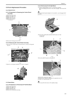
3.3 Parts Replacement Procedure 3.3.1 Scanner Unit 3.3.1.1 Preparation for Removing the Control Panel Assembly 0016-5024 1) Remove the front cover. 2) Remove the right cover. 3) Remove the left cover. 4) Remove the rear cover. 5) Remove the frame [1]. - 11 screws [2] Chapter 3 3.3.2.2 Removing the Flat Bed Motor 0016-5033 1) Open the copyboard glass cover [1], and remove it upward. Pull out the hinge [2] on the left side while keeping it tilted toward the back. Place the detached copyboard glass cover on cloth etc. not to damage the bottom sheet. F-3-4 6) Remove the Analog processor PCB. 3.3.1.2 Removing the Control Panel Assembly 0016-5025 1) Disconnect the 5 connectors [1], and remove the 1 screw [2] of the grounding wire. F-3-7 2) Reverse the copyboard [1] and detach the bottom cover [4]. - 2 screws [2] - 5 claws [3] F-3-5 2) Open the control panel assembly [1] to remove it upward. F-3-8 3) Free the cable [1] from the cable guide [2]. F-3-6 3.3.2 Book Motor 3.3.2.1 Preparation for Removing the Flat Bed Motor 0016-5032 1) Remove the front cover. 2) Remove the right cover. 3) Remove the left cover. 4) Remove the rear cover. 5) Remove the control panel assembly. F-3-9 4) Reverse the copyboard [1] again. 5) Remove the 4 screws [2], and detach the copyboard cover [3]. 6) Remove the copyboard glass [4]. Do not make dirty the bottom of the copyboard glass. 3-5
-
 1
1 -
2
-
3
-
4
-
5
-
6
-
7
-
8
-
9
-
10
-
11
-
12
-
13
-
14
-
15
-
16
-
17
-
18
-
19
-
20
-
21
-
22
-
23
-
24
-
25
-
26
-
27
-
28
-
29
-
30
-
31
-
32
-
33
-
34
-
35
-
36
-
37
-
38
-
39
-
 40
40 -
 41
41 -
 42
42 -
 43
43 -
 44
44 -
 45
45 -
 46
46 -
 47
47 -
 48
48 -
 49
49 -
 50
50 -
51
-
52
-
53
-
54
-
55
-
56
-
57
-
58
-
59
-
60
-
61
-
62
-
63
-
64
-
65
-
66
-
67
-
68
-
69
-
70
-
71
-
72
-
73
-
74
-
75
-
76
-
77
-
78
-
79
-
80
-
81
-
82
-
83
-
84
-
85
-
86
-
87
-
88
-
89
-
90
-
91
-
92
-
93
-
94
-
95
-
96
-
97
-
98
-
99
-
100
-
101
-
102
-
103
-
104
-
105
-
106
-
107
-
108
-
109
-
110
-
111
-
112
-
113
-
114
-
115
-
116
-
117
-
118
-
119
-
120
-
121
-
122
-
123
-
124
-
125
-
126
-
127
-
128
-
129
-
130
-
131
-
132
-
133
-
134
-
135
-
136
-
137
-
138
-
139
-
140
-
141
-
142
-
143
-
144
-
145
-
146
-
147
-
148
-
149
-
150
-
151
-
152
-
153
-
154
-
155
-
156
-
157
-
158
-
159
-
160
-
161
-
162
-
163
-
164
-
165
-
166
-
167
-
168
-
169
-
170
-
171
-
172
-
173
-
174
-
175
-
176
-
177
-
178
-
179
-
180
-
181
-
182
 |
 |
