Canon PC430 Service Manual - Page 149
II. STANDARDS AND ADJUSTMENTS, A. Mechanical
 |
UPC - 030275150322
View all Canon PC430 manuals
Add to My Manuals
Save this manual to your list of manuals |
Page 149 highlights
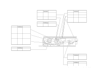
CHAPTER 10 TROUBLESHOOTING II. STANDARDS AND ADJUSTMENTS A. Mechanical 1. Image Leading Edge Non-Image Width (position of white paint on back of glass) The leading edge non-image width must be 2.0 ±1.0 mm when the Test Sheet is copied. 2.0 ± 1.0 [mm] Figure 10-201A The leading edge non-image width is determined by the position of the white paint found behind the copyboard glass. Copyboard glass 2mm Size index White paint Figure 10-202A 2. Image Leading Edge Margin (point of detection for registration) The leading edge margin must be 0.2 to 5.0 mm when the Test Sheet is copied. To adjust, move the position of the registration cam. 0.2 to 5.0 [mm] Figure 10-203A COPYRIGHT © 1998 CANON INC. CANON PC400/420/430,FC200/220 REV.0 JAN.1998 PRINTED IN JAPAN (IMPRIME AU JAPON) 10-5
-
 1
1 -
2
-
3
-
4
-
5
-
6
-
7
-
8
-
9
-
10
-
11
-
12
-
13
-
14
-
15
-
16
-
17
-
18
-
19
-
20
-
21
-
22
-
23
-
24
-
25
-
26
-
27
-
28
-
29
-
30
-
31
-
32
-
33
-
34
-
35
-
36
-
37
-
38
-
39
-
40
-
41
-
42
-
43
-
44
-
45
-
46
-
47
-
48
-
49
-
50
-
51
-
52
-
53
-
54
-
55
-
56
-
57
-
58
-
59
-
60
-
61
-
62
-
63
-
64
-
65
-
66
-
67
-
68
-
69
-
70
-
71
-
72
-
73
-
74
-
75
-
76
-
77
-
78
-
79
-
80
-
81
-
82
-
83
-
84
-
85
-
86
-
87
-
88
-
89
-
90
-
91
-
92
-
93
-
94
-
95
-
96
-
97
-
98
-
99
-
100
-
101
-
102
-
103
-
104
-
105
-
106
-
107
-
108
-
109
-
110
-
111
-
112
-
113
-
114
-
115
-
116
-
117
-
118
-
119
-
120
-
121
-
122
-
123
-
124
-
125
-
126
-
127
-
128
-
129
-
130
-
131
-
132
-
133
-
134
-
135
-
136
-
137
-
138
-
139
-
140
-
141
-
142
-
143
-
 144
144 -
 145
145 -
 146
146 -
 147
147 -
 148
148 -
 149
149 -
 150
150 -
 151
151 -
 152
152 -
 153
153 -
 154
154 -
155
-
156
-
157
-
158
-
159
-
160
-
161
-
162
-
163
-
164
-
165
-
166
-
167
-
168
-
169
-
170
-
171
-
172
-
173
-
174
-
175
-
176
-
177
-
178
-
179
-
180
-
181
-
182
-
183
-
184
-
185
-
186
-
187
-
188
-
189
-
190
-
191
-
192
-
193
-
194
-
195
-
196
-
197
 |
 |
