Canon PC430 Service Manual - Page 171
Pick-up fails., The scanning lamp fails to go ON., See Pick-Up Assembly
 |
UPC - 030275150322
View all Canon PC430 manuals
Add to My Manuals
Save this manual to your list of manuals |
Page 171 highlights
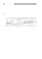
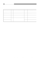
CHAPTER 10 TROUBLESHOOTING 7. Pick-up fails. Cause Main motor (M1) Step Checks 1 Move the copyboard to the left until it stops, and open the top cover. Does the pick-up roller rotate when the door switch is turned ON and the Copy Start key is pressed at the correct pick-up timing? 2 Is the main motor rotating? Pick-up sensor (Q131) Pick-up solenoid (SL1; PC420/430/FC220), Registration solenoid (SL1; PC400/FC200) DC controller/ DC power supply PCB 3 Does the copier operate normally when the pick-up sensor (Q131) is blocked with paper? 4 Set the meter to the '30VDC' range. Does the voltage between J201-6 (+) and J201-7 (-) on the DC controller/DC power supply PCB change to about 24 V at pick-up timing? YES/NO Remedies YES See "Pick-Up Assembly" in "Troubleshooting Feeding Faults." NO YES See "The main motor fails to rotate." Check the sensor lever. YES NO Check the spring clutch in the registration assembly and pick-up assembly; if normal, replace the solenoid. Check the wiring from the solenoid to the DC controller/DC power supply PCB; if normal, replace the DC controller/DC power supply PCB. 8. The scanning lamp fails to go ON. Cause Scanning lamp (LA1-LA8) Scanning lamp (LA1-LA8) DC controller/DC power supply PCB Connector Step Checks 1 Is the scanning lamp unit attached correctly? 2 Is the scanning lamp black? 3 Is the connector of the scanning lamp connected firmly? YES/NO Remedies NO Re-attach the lamp unit. YES YES NO Replace the scanning lamp unit. Replace the DC controller/ DC power supply PCB. Re-connect the connector. COPYRIGHT © 1998 CANON INC. CANON PC400/420/430,FC200/220 REV.0 JAN.1998 PRINTED IN JAPAN (IMPRIME AU JAPON) 10-27
-
 1
1 -
2
-
3
-
4
-
5
-
6
-
7
-
8
-
9
-
10
-
11
-
12
-
13
-
14
-
15
-
16
-
17
-
18
-
19
-
20
-
21
-
22
-
23
-
24
-
25
-
26
-
27
-
28
-
29
-
30
-
31
-
32
-
33
-
34
-
35
-
36
-
37
-
38
-
39
-
40
-
41
-
42
-
43
-
44
-
45
-
46
-
47
-
48
-
49
-
50
-
51
-
52
-
53
-
54
-
55
-
56
-
57
-
58
-
59
-
60
-
61
-
62
-
63
-
64
-
65
-
66
-
67
-
68
-
69
-
70
-
71
-
72
-
73
-
74
-
75
-
76
-
77
-
78
-
79
-
80
-
81
-
82
-
83
-
84
-
85
-
86
-
87
-
88
-
89
-
90
-
91
-
92
-
93
-
94
-
95
-
96
-
97
-
98
-
99
-
100
-
101
-
102
-
103
-
104
-
105
-
106
-
107
-
108
-
109
-
110
-
111
-
112
-
113
-
114
-
115
-
116
-
117
-
118
-
119
-
120
-
121
-
122
-
123
-
124
-
125
-
126
-
127
-
128
-
129
-
130
-
131
-
132
-
133
-
134
-
135
-
136
-
137
-
138
-
139
-
140
-
141
-
142
-
143
-
144
-
145
-
146
-
147
-
148
-
149
-
150
-
151
-
152
-
153
-
154
-
155
-
156
-
157
-
158
-
159
-
160
-
161
-
162
-
163
-
164
-
165
-
 166
166 -
 167
167 -
 168
168 -
 169
169 -
 170
170 -
 171
171 -
 172
172 -
 173
173 -
 174
174 -
 175
175 -
 176
176 -
177
-
178
-
179
-
180
-
181
-
182
-
183
-
184
-
185
-
186
-
187
-
188
-
189
-
190
-
191
-
192
-
193
-
194
-
195
-
196
-
197
 |
 |
