Canon PC430 Service Manual - Page 52
B. Operations, C. Controlling the Intensity of the Scanning Lamp VR604
 |
UPC - 030275150322
View all Canon PC430 manuals
Add to My Manuals
Save this manual to your list of manuals |
Page 52 highlights
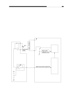
CHAPTER 3 EXPOSURE SYSTEM B. Operations 1. Turning the Scanning Lamp ON and OFF • Square waves of the LAPWM command corresponding to the output of the amplifi er circuit are generated to the lamp driver circuit. (Q143 ON) Current flows into the filament of the lamp, causing the fluorescent lamp to go ON at high frequency. 2. Controlling the Intensity of the Scanning Lamp • If the intensity of the lamp is low when the lamp goes ON, Initial power of the intensity sensor PD601 is low. Output voltage of the amplifier circuit is high. Duty ratio (H) of the output of the microprocessor (LAPWM com mand) grows high. Current flowing to the lamp increases. • If the intensity of the lamp is high when the lamp goes ON, Initial power of the intensity sensor PD601 is high. Output voltage of the amplifier circuit is low. Duty ratio (H) of the output of the microprocessor (LAPWM com mand) grows low. Current flowing to the lamp decreases. • If the microprocessor finds out that the scanning lamp has remained on for 2 min at such times as not prescribed, it activates the self diagnostic mechanism; the results are indicated by 'E6' for the PC420/430/FC220 and 'JAM' for the PC400/FC200. C. Controlling the Intensity of the Scanning Lamp (VR604) You must adjust the intensity of the lamp if you have replaced the scanning lamp unit, intensity sensor or control panel PCB; see p.10-6. Note: You must adjust the AE mechanism after adjusting the intensity. (PC420/430/FC220) 3-8 COPYRIGHT © 1998 CANON INC. CANON PC400/420/430,FC200/220 REV.0 JAN.1998 PRINTED IN JAPAN (IMPRIME AU JAPON)
-
 1
1 -
2
-
3
-
4
-
5
-
6
-
7
-
8
-
9
-
10
-
11
-
12
-
13
-
14
-
15
-
16
-
17
-
18
-
19
-
20
-
21
-
22
-
23
-
24
-
25
-
26
-
27
-
28
-
29
-
30
-
31
-
32
-
33
-
34
-
35
-
36
-
37
-
38
-
39
-
40
-
41
-
42
-
43
-
44
-
45
-
46
-
 47
47 -
 48
48 -
 49
49 -
 50
50 -
 51
51 -
 52
52 -
 53
53 -
 54
54 -
 55
55 -
 56
56 -
 57
57 -
58
-
59
-
60
-
61
-
62
-
63
-
64
-
65
-
66
-
67
-
68
-
69
-
70
-
71
-
72
-
73
-
74
-
75
-
76
-
77
-
78
-
79
-
80
-
81
-
82
-
83
-
84
-
85
-
86
-
87
-
88
-
89
-
90
-
91
-
92
-
93
-
94
-
95
-
96
-
97
-
98
-
99
-
100
-
101
-
102
-
103
-
104
-
105
-
106
-
107
-
108
-
109
-
110
-
111
-
112
-
113
-
114
-
115
-
116
-
117
-
118
-
119
-
120
-
121
-
122
-
123
-
124
-
125
-
126
-
127
-
128
-
129
-
130
-
131
-
132
-
133
-
134
-
135
-
136
-
137
-
138
-
139
-
140
-
141
-
142
-
143
-
144
-
145
-
146
-
147
-
148
-
149
-
150
-
151
-
152
-
153
-
154
-
155
-
156
-
157
-
158
-
159
-
160
-
161
-
162
-
163
-
164
-
165
-
166
-
167
-
168
-
169
-
170
-
171
-
172
-
173
-
174
-
175
-
176
-
177
-
178
-
179
-
180
-
181
-
182
-
183
-
184
-
185
-
186
-
187
-
188
-
189
-
190
-
191
-
192
-
193
-
194
-
195
-
196
-
197
 |
 |
