Canon PC770 Service Manual - Page 149
Electrical, System
 |
View all Canon PC770 manuals
Add to My Manuals
Save this manual to your list of manuals |
Page 149 highlights
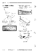
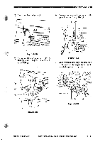
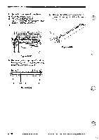
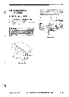
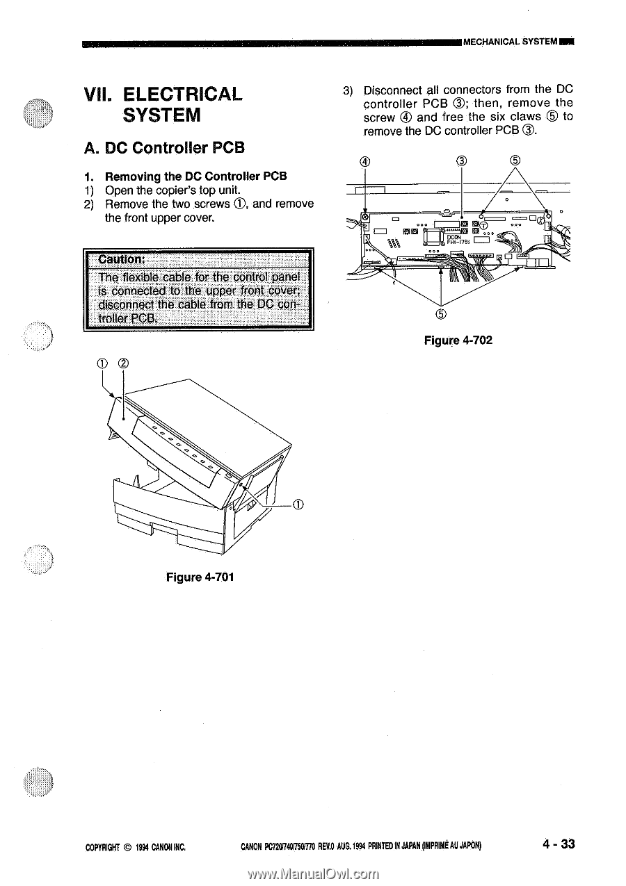
MECHANICAL SYSTEMMI VII. ELECTRICAL SYSTEM A. DC Controller PCB 1. Removing the DC Controller PCB 1) Open the copier's top unit. 2) Remove the two screws C), and remove the front upper cover. Caution: The flexible cable for the control panel is connected to the upper front cover; disconnect the cable from the DC controller PCB. CD 0 3) Disconnect all connectors from the DC controller PCB a then, remove the screw ® and free the six claws © to remove the DC controller PCB 0. 3 PF017, *1° O0 Figure 4-702 Figure 4-701 COPYRIGHT © 1994 CANONINC. CANON PC720R40R501770 REVA AUG.1994 PRINTEDINJAPAN(INPRIMEAUJAPON) 4 - 33
-
 1
1 -
2
-
3
-
4
-
5
-
6
-
7
-
8
-
9
-
10
-
11
-
12
-
13
-
14
-
15
-
16
-
17
-
18
-
19
-
20
-
21
-
22
-
23
-
24
-
25
-
26
-
27
-
28
-
29
-
30
-
31
-
32
-
33
-
34
-
35
-
36
-
37
-
38
-
39
-
40
-
41
-
42
-
43
-
44
-
45
-
46
-
47
-
48
-
49
-
50
-
51
-
52
-
53
-
54
-
55
-
56
-
57
-
58
-
59
-
60
-
61
-
62
-
63
-
64
-
65
-
66
-
67
-
68
-
69
-
70
-
71
-
72
-
73
-
74
-
75
-
76
-
77
-
78
-
79
-
80
-
81
-
82
-
83
-
84
-
85
-
86
-
87
-
88
-
89
-
90
-
91
-
92
-
93
-
94
-
95
-
96
-
97
-
98
-
99
-
100
-
101
-
102
-
103
-
104
-
105
-
106
-
107
-
108
-
109
-
110
-
111
-
112
-
113
-
114
-
115
-
116
-
117
-
118
-
119
-
120
-
121
-
122
-
123
-
124
-
125
-
126
-
127
-
128
-
129
-
130
-
131
-
132
-
133
-
134
-
135
-
136
-
137
-
138
-
139
-
140
-
141
-
142
-
143
-
 144
144 -
 145
145 -
 146
146 -
 147
147 -
 148
148 -
 149
149 -
 150
150 -
 151
151 -
 152
152 -
 153
153 -
 154
154 -
155
-
156
-
157
-
158
-
159
-
160
-
161
-
162
-
163
-
164
-
165
-
166
-
167
-
168
-
169
-
170
-
171
-
172
-
173
-
174
-
175
-
176
-
177
-
178
-
179
-
180
-
181
-
182
-
183
-
184
-
185
-
186
-
187
-
188
-
189
-
190
-
191
-
192
-
193
-
194
-
195
-
196
-
197
-
198
-
199
-
200
 |
 |
MECHANICAL
SYSTEM
MI
VII.
ELECTRICAL
SYSTEM
A.
DC
Controller
PCB
1.
Removing
the
DC
Controller
PCB
1)
Open
the
copier's
top
unit.
2)
Remove
the
two
screws
C),
and
remove
the
front
upper
cover.
Caution:
The
flexible
cable
for
the
control
panel
is
connected
to
the
upper
front
cover;
disconnect
the
cable
from
the
DC
con-
troller
PCB.
CD
0
Figure
4-701
3)
Disconnect
all
connectors
from
the
DC
controller
PCB
a
then,
remove
the
screw
®
and
free
the
six
claws
©
to
remove
the
DC
controller
PCB
0.
3
PF017,
*
1
°
Figure
O0
4-702
COPYRIGHT
©
1994
CANON
INC.
CANON
PC720R40R501770
REVA
AUG.1994
PRINTED
IN
JAPAN
(INPRIME
AU
JAPON)
4
-
33