Canon PC770 Service Manual - Page 169
General, Timing, Chart
 |
View all Canon PC770 manuals
Add to My Manuals
Save this manual to your list of manuals |
Page 169 highlights
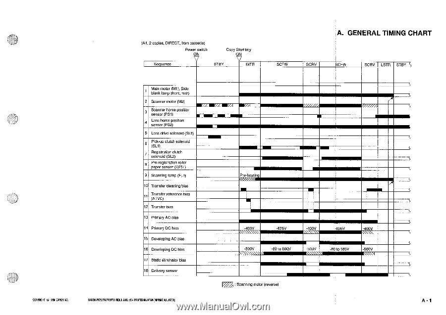
(A4, 2 copies, DIRECT, from cassette) Power switch ON Copy Start key ON Sequence STBY INTR A. GENERAL TIMING CHART SCFW SCRV SCFW SCRV LSTR STBY COPYRIGHT t994 CANON INC. 1 Main motor (M1), Side blank lamp (front, rear) 2 Scanner motor (M2) Scanner home position sensor (PS1) 1 Lens home position sensor (PS2) 5 Lens drive solenoid (SL3) 6 Pick-up clutch solenoid (SL1) Registration clutch solenoid (SL2) 8 Pre-registration roller paper sensor (Q751) 9 Scanning lamp (FL1) 10 Transfer cleaning bias 11 Transfer reference bias (ATVC) 12 Transfer bias 13 Primary AC bias 14 Primary DC bias 15 Developing AC bias 16 Developing DC bias 17 Static eliminator bias 18 Delivery sensor CANON PC720174017501770RDA AUG.1994 PRINTED IN JAPAN (MPRIME AU JAPON) ME Pre-heatin -400V -625V -400V -625V -400V -500V -80 to 580V -500V -80 to 580V -500V : Scanning motor (reverse) A - 1
-
 1
1 -
2
-
3
-
4
-
5
-
6
-
7
-
8
-
9
-
10
-
11
-
12
-
13
-
14
-
15
-
16
-
17
-
18
-
19
-
20
-
21
-
22
-
23
-
24
-
25
-
26
-
27
-
28
-
29
-
30
-
31
-
32
-
33
-
34
-
35
-
36
-
37
-
38
-
39
-
40
-
41
-
42
-
43
-
44
-
45
-
46
-
47
-
48
-
49
-
50
-
51
-
52
-
53
-
54
-
55
-
56
-
57
-
58
-
59
-
60
-
61
-
62
-
63
-
64
-
65
-
66
-
67
-
68
-
69
-
70
-
71
-
72
-
73
-
74
-
75
-
76
-
77
-
78
-
79
-
80
-
81
-
82
-
83
-
84
-
85
-
86
-
87
-
88
-
89
-
90
-
91
-
92
-
93
-
94
-
95
-
96
-
97
-
98
-
99
-
100
-
101
-
102
-
103
-
104
-
105
-
106
-
107
-
108
-
109
-
110
-
111
-
112
-
113
-
114
-
115
-
116
-
117
-
118
-
119
-
120
-
121
-
122
-
123
-
124
-
125
-
126
-
127
-
128
-
129
-
130
-
131
-
132
-
133
-
134
-
135
-
136
-
137
-
138
-
139
-
140
-
141
-
142
-
143
-
144
-
145
-
146
-
147
-
148
-
149
-
150
-
151
-
152
-
153
-
154
-
155
-
156
-
157
-
158
-
159
-
160
-
161
-
162
-
163
-
 164
164 -
 165
165 -
 166
166 -
 167
167 -
 168
168 -
 169
169 -
 170
170 -
 171
171 -
 172
172 -
 173
173 -
 174
174 -
175
-
176
-
177
-
178
-
179
-
180
-
181
-
182
-
183
-
184
-
185
-
186
-
187
-
188
-
189
-
190
-
191
-
192
-
193
-
194
-
195
-
196
-
197
-
198
-
199
-
200
 |
 |