Canon PC770 Service Manual - Page 36
Separation, Fixing
 |
View all Canon PC770 manuals
Add to My Manuals
Save this manual to your list of manuals |
Page 36 highlights
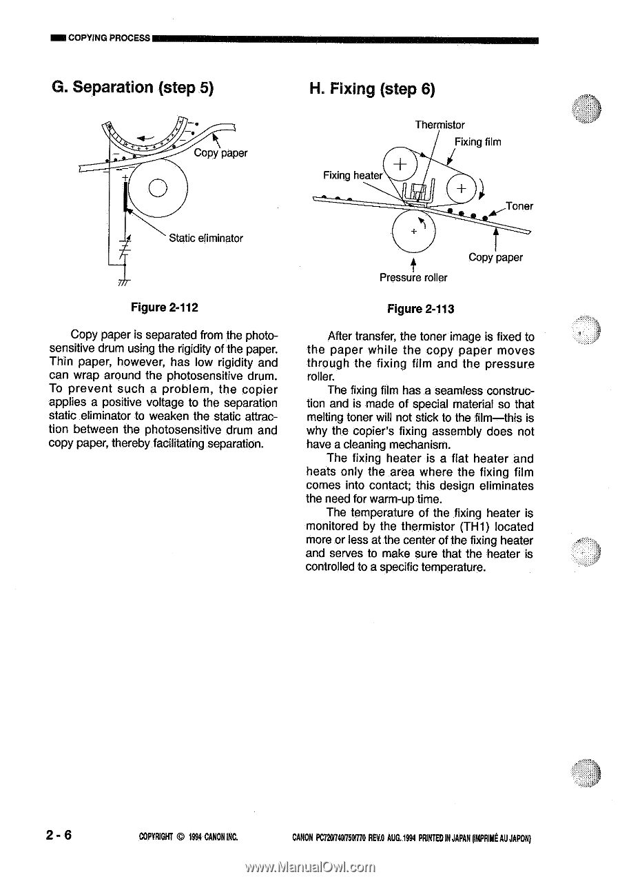
MI COPYING PROCESS G. Separation (step 5) H. Fixing (step 6) Copy paper O Fixing heater Thermistor Fixing film Toner Static eliminator Figure 2-112 Copy paper is separated from the photosensitive drum using the rigidity of the paper. Thin paper, however, has low rigidity and can wrap around the photosensitive drum. To prevent such a problem, the copier applies a positive voltage to the separation static eliminator to weaken the static attraction between the photosensitive drum and copy paper, thereby facilitating separation. Pressure roller Copy paper Figure 2-113 After transfer, the toner image is fixed to the paper while the copy paper moves through the fixing film and the pressure roller. The fixing film has a seamless construction and is made of special material so that melting toner will not stick to the film-this is why the copier's fixing assembly does not have a cleaning mechanism. The fixing heater is a flat heater and heats only the area where the fixing film comes into contact; this design eliminates the need for warm-up time. The temperature of the fixing heater is monitored by the thermistor (TH1) located more or less at the center of the fixing heater and serves to make sure that the heater is controlled to a specific temperature. 2 - 6 COPYRIGHT © 1994 CANON INC. CANON PC720,740/750i770 REY.0 AUG.1994 PRINTEDIN JAPAN DIARIME AU JAPON)
-
 1
1 -
2
-
3
-
4
-
5
-
6
-
7
-
8
-
9
-
10
-
11
-
12
-
13
-
14
-
15
-
16
-
17
-
18
-
19
-
20
-
21
-
22
-
23
-
24
-
25
-
26
-
27
-
28
-
29
-
30
-
 31
31 -
 32
32 -
 33
33 -
 34
34 -
 35
35 -
 36
36 -
 37
37 -
 38
38 -
 39
39 -
 40
40 -
 41
41 -
42
-
43
-
44
-
45
-
46
-
47
-
48
-
49
-
50
-
51
-
52
-
53
-
54
-
55
-
56
-
57
-
58
-
59
-
60
-
61
-
62
-
63
-
64
-
65
-
66
-
67
-
68
-
69
-
70
-
71
-
72
-
73
-
74
-
75
-
76
-
77
-
78
-
79
-
80
-
81
-
82
-
83
-
84
-
85
-
86
-
87
-
88
-
89
-
90
-
91
-
92
-
93
-
94
-
95
-
96
-
97
-
98
-
99
-
100
-
101
-
102
-
103
-
104
-
105
-
106
-
107
-
108
-
109
-
110
-
111
-
112
-
113
-
114
-
115
-
116
-
117
-
118
-
119
-
120
-
121
-
122
-
123
-
124
-
125
-
126
-
127
-
128
-
129
-
130
-
131
-
132
-
133
-
134
-
135
-
136
-
137
-
138
-
139
-
140
-
141
-
142
-
143
-
144
-
145
-
146
-
147
-
148
-
149
-
150
-
151
-
152
-
153
-
154
-
155
-
156
-
157
-
158
-
159
-
160
-
161
-
162
-
163
-
164
-
165
-
166
-
167
-
168
-
169
-
170
-
171
-
172
-
173
-
174
-
175
-
176
-
177
-
178
-
179
-
180
-
181
-
182
-
183
-
184
-
185
-
186
-
187
-
188
-
189
-
190
-
191
-
192
-
193
-
194
-
195
-
196
-
197
-
198
-
199
-
200
 |
 |