Canon PC770 Service Manual - Page 56
Current, switching, circuit, Motor, driver, COPYRIGHT, CANONINC., CANON PC7207401150IT10,
 |
View all Canon PC770 manuals
Add to My Manuals
Save this manual to your list of manuals |
Page 56 highlights
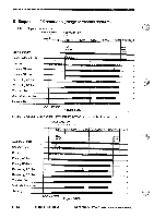
=OPERATIONS AND TIMING 4. Driving the Scanner Motor a. Outline The scanner motor (M2) is a 4-phase stepping motor. It is turned on or off and its direction and speed of rotation is changed by controlling the output timing of the drive power supply SC-COMA and SC-COMB and pulse signals A, A*, B, and B*. b. Operation The microprocessor (Q101) on the DC controller PCB receives such instructions as copying modes and reproduction ratios from the control panel circuit; and, in response, it sends drive pulses to the scanner motor (M2) through the motor drive circuit. The scanner motor is a 4-phase stepping motor, and controls the direction and speed of scanning by changing the frequency and the sequence of drive pulses (SC-A through SC-B*). The motor drive voltage on/off switching circuit supplies power to drive the motor and removes power to stop it. The current switching circuit sets the current flowing to the motor according to the speed of rotation; the motor driver circuit is used to control the rated current according to the setting. (Q101) DC controller PCB Voltage on/off signal 24V Motor drive voltage on/off switching circuit J101 SC-COMA I SC-COMB A A* Microprocessor B B* (Q109) 5V Current switching signal ► Current switching circuit Motor driver circuit SC-A SC-A* Q.9 SC-B SC-B` g M2 Figure 3-207 3 - 16 COPYRIGHT © 1994 CANONINC. CANON PC7207401150IT10REV.0 AUG.1994 PRINTEDINJAPAN(mput AU JAPAN)
-
 1
1 -
2
-
3
-
4
-
5
-
6
-
7
-
8
-
9
-
10
-
11
-
12
-
13
-
14
-
15
-
16
-
17
-
18
-
19
-
20
-
21
-
22
-
23
-
24
-
25
-
26
-
27
-
28
-
29
-
30
-
31
-
32
-
33
-
34
-
35
-
36
-
37
-
38
-
39
-
40
-
41
-
42
-
43
-
44
-
45
-
46
-
47
-
48
-
49
-
50
-
 51
51 -
 52
52 -
 53
53 -
 54
54 -
 55
55 -
 56
56 -
 57
57 -
 58
58 -
 59
59 -
 60
60 -
 61
61 -
62
-
63
-
64
-
65
-
66
-
67
-
68
-
69
-
70
-
71
-
72
-
73
-
74
-
75
-
76
-
77
-
78
-
79
-
80
-
81
-
82
-
83
-
84
-
85
-
86
-
87
-
88
-
89
-
90
-
91
-
92
-
93
-
94
-
95
-
96
-
97
-
98
-
99
-
100
-
101
-
102
-
103
-
104
-
105
-
106
-
107
-
108
-
109
-
110
-
111
-
112
-
113
-
114
-
115
-
116
-
117
-
118
-
119
-
120
-
121
-
122
-
123
-
124
-
125
-
126
-
127
-
128
-
129
-
130
-
131
-
132
-
133
-
134
-
135
-
136
-
137
-
138
-
139
-
140
-
141
-
142
-
143
-
144
-
145
-
146
-
147
-
148
-
149
-
150
-
151
-
152
-
153
-
154
-
155
-
156
-
157
-
158
-
159
-
160
-
161
-
162
-
163
-
164
-
165
-
166
-
167
-
168
-
169
-
170
-
171
-
172
-
173
-
174
-
175
-
176
-
177
-
178
-
179
-
180
-
181
-
182
-
183
-
184
-
185
-
186
-
187
-
188
-
189
-
190
-
191
-
192
-
193
-
194
-
195
-
196
-
197
-
198
-
199
-
200
 |
 |
