Canon PIXMA MP800 Service Manual - Page 4
Table Of Contents, Part 1, Maintenance, Technical Reference, Appendix - logic board
 |
View all Canon PIXMA MP800 manuals
Add to My Manuals
Save this manual to your list of manuals |
Page 4 highlights
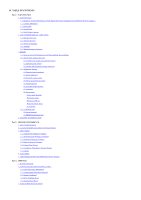
II. TABLE OF CONTENTS Part 1: MAINTENANCE 1. MAINTENANCE 1-1. Adjustment, Periodic Maintenance, Periodic Replacement Parts, and Replacement Consumables by Service Engineer 1-2. Customer Maintenance 1-3. Product Life 1-4. Special Tools 1-5. Serial Number Location 2. LIST OF ERROR DISPLAY / INDICATION 2-1. Operator Call Errors 2-2. Service Call Errors 2-3. Other Error Messages 2-4. Warnings 2-5. Troubleshooting by Symptom 3. REPAIR 3-1. Notes on Service Part Replacement (and Disassembling / Reassembling) 3-2. Special Notes on Repair Servicing (1) External cover, scanner unit, and FAU removal (2) Operation panel removal (3) Flexible cable and harness wiring, connection 3-3. Adjustment / Settings (1) Paper feed motor adjustment (2) Grease application (3) Waste ink counter setting (4) White sponge sheet attachment (5) Solenoid position (6) Front door damper position (7) User mode (8) Service mode Service mode operation Destination settings Button and LCD test Waste ink amount setting LF correction 3-4. Verification Items (1) Service test print (2) EEPROM information print 4. MACHINE TRANSPORTATION Part 2: TECHNICAL REFERENCE 1. NEW TECHNOLOGIES 2. CLEANING MODE AND AMOUNT OF INK PURGED 3. PRINT MODE 3-1. Normal Color Printing via Computer 3-2. Normal Grayscale Printing via Computer 3-3. Borderless Printing via Computer 3-4. Duplex Printing via Computer 3-5. Camera Direct Printing 3-6. Card Direct / Photo Direct / Wireless Printing 3-7. Copying 4. SCAN MODE 5. FAQ (Problems Specific to the MP800 and Corrective Actions) Part 3: APPENDIX 1. BLOCK DIAGRAM 2. CONNECTOR LOCATION AND PIN LAYOUT 2-1. Logic Board Ass'y (Main Board) 2-2. Carriage Board (Print Head Connector) 2-3. Memory Card Board 2-4. IrDA / PictBridge Board 2-5. Operation Panel Board 3. PIXMA MP800 SPECIFICATIONS
-
 1
1 -
 2
2 -
 3
3 -
 4
4 -
 5
5 -
 6
6 -
 7
7 -
 8
8 -
 9
9 -
 10
10 -
11
-
12
-
13
-
14
-
15
-
16
-
17
-
18
-
19
-
20
-
21
-
22
-
23
-
24
-
25
-
26
-
27
-
28
-
29
-
30
-
31
-
32
-
33
-
34
-
35
-
36
-
37
-
38
-
39
-
40
-
41
-
42
-
43
-
44
-
45
-
46
-
47
-
48
-
49
-
50
-
51
-
52
-
53
-
54
-
55
-
56
-
57
-
58
-
59
-
60
-
61
-
62
 |
 |
