Cisco 8540 User Guide - Page 21
Route Processors, Switch Modules
 |
View all Cisco 8540 manuals
Add to My Manuals
Save this manual to your list of manuals |
Page 21 highlights
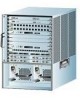
32601 Chapter 1 Product Overview Route Processors Route Processors The route processor contains most of the system memory components and the main system processor, which includes the network management processor for the system software. You can install up to two route processors in slots 4 and 8 of the chassis. The chassis supports fault tolerance by allowing a secondary (or redundant) route processor to take over if the primary route processor fails. This redundant route processor runs in standby mode. Figure 1-2 shows the route processor, which maintains and executes the management functions that control the chassis. Figure 1-2 Route Processor STATUS ASCTATNIVDEBY ROUTE PROCESSOR SLOT 1 SLOT 0 TX CONSOLE RX LINK Switch Modules You can install up to three switch modules in slots 5 to 7 of the chassis. Two switch modules are required for operation. By default, switch modules 5 and 7 are primary and switch module 6 runs in standby. The third switch module provides redundancy for only one of the two active modules in the chassis. The standby switch module automatically becomes active in the event that you remove one of the switch modules from the system. To force the standby switch module to become active, use the redundancy preferred-switch-card-slots command. Figure 1-3 shows the switch module. Figure 1-3 Switch Module STATUS ASCTATNIVDEBY SWITCH PROCESSOR 32602 78-6134-03 Catalyst 8540 Chassis Installation Guide 1-3
-
 1
1 -
2
-
3
-
4
-
5
-
6
-
7
-
8
-
9
-
10
-
11
-
12
-
13
-
14
-
15
-
 16
16 -
 17
17 -
 18
18 -
 19
19 -
 20
20 -
 21
21 -
 22
22 -
 23
23 -
 24
24 -
 25
25 -
 26
26 -
27
-
28
-
29
-
30
-
31
-
32
-
33
-
34
-
35
-
36
-
37
-
38
-
39
-
40
-
41
-
42
-
43
-
44
-
45
-
46
-
47
-
48
-
49
-
50
-
51
-
52
-
53
-
54
-
55
-
56
-
57
-
58
-
59
-
60
-
61
-
62
-
63
-
64
 |
 |
