Cisco 8540 User Guide - Page 35
When installing the unit, the ground connection must always be, made first and disconnected last.
 |
View all Cisco 8540 manuals
Add to My Manuals
Save this manual to your list of manuals |
Page 35 highlights
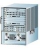
Chapter 2 Installing the Chassis Connecting Power to the Chassis Step 4 Step 5 Attach the appropriate lugs to the DC-input wires. (See Figure 2-7.) Wire the DC-input conductors from the top of the terminal block as follows: • Ground wire to ground terminal • Return wire to "+" terminal • Battery wire to "−" terminal Figure 2-7 DC Power Supply (Terminal Block Cover Not Shown) Terminal block 15708 Power o switch INPUT OK FAN OUTPUT OK FAIL LEDs Warning When installing the unit, the ground connection must always be made first and disconnected last. Note Use 8 AWG, 90° , copper conductor for the above connections. Note Route the wires from the top of the terminal block so that you do not obstruct access to the chassis power switch. Step 6 Reinstall the terminal block cover after ensuring that all wire connections are secure. 78-6134-03 Catalyst 8540 Chassis Installation Guide 2-11
-
 1
1 -
2
-
3
-
4
-
5
-
6
-
7
-
8
-
9
-
10
-
11
-
12
-
13
-
14
-
15
-
16
-
17
-
18
-
19
-
20
-
21
-
22
-
23
-
24
-
25
-
26
-
27
-
28
-
29
-
 30
30 -
 31
31 -
 32
32 -
 33
33 -
 34
34 -
 35
35 -
 36
36 -
 37
37 -
 38
38 -
 39
39 -
 40
40 -
41
-
42
-
43
-
44
-
45
-
46
-
47
-
48
-
49
-
50
-
51
-
52
-
53
-
54
-
55
-
56
-
57
-
58
-
59
-
60
-
61
-
62
-
63
-
64
 |
 |
