Cisco 8540 User Guide - Page 43
Removing the DC Power Supply
 |
View all Cisco 8540 manuals
Add to My Manuals
Save this manual to your list of manuals |
Page 43 highlights
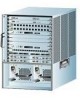
Chapter 3 Maintaining the Chassis Replacing Power Supplies Removing the DC Power Supply To remove a DC power supply, follow these steps: Step 1 Step 2 Step 3 Verify that the power is off to the DC input line furnishing power to the power supply you are removing. Turn off the power switch on the power supply you are removing. (See Figure 3-3.) Remove the terminal block cover by removing the two screws at the top and bottom of the terminal block. (See Figure 3-3.) Figure 3-3 DC Power Supply 17116 Terminal block cover Power switch o INPUT OK FAN OUTPUT OK FAIL LEDs Captive screw Warning When installing the unit, the ground connection must always be made first and disconnected last. Step 4 Step 5 Step 6 Disconnect the input wires from the terminal block. Loosen the captive screw on the power supply with a screwdriver. Grasp the power supply handle with one hand. Slowly pull the power supply out of the chassis toward you. While holding the power supply handle with one hand, place your other hand underneath to support the bottom of the supply. (See Figure 3-2.) 78-6134-03 Catalyst 8540 Chassis Installation Guide 3-5
-
 1
1 -
2
-
3
-
4
-
5
-
6
-
7
-
8
-
9
-
10
-
11
-
12
-
13
-
14
-
15
-
16
-
17
-
18
-
19
-
20
-
21
-
22
-
23
-
24
-
25
-
26
-
27
-
28
-
29
-
30
-
31
-
32
-
33
-
34
-
35
-
36
-
37
-
 38
38 -
 39
39 -
 40
40 -
 41
41 -
 42
42 -
 43
43 -
 44
44 -
 45
45 -
 46
46 -
 47
47 -
 48
48 -
49
-
50
-
51
-
52
-
53
-
54
-
55
-
56
-
57
-
58
-
59
-
60
-
61
-
62
-
63
-
64
 |
 |
