Cisco IE-3000-4TC Installation Guide - Page 16
Console Port, LEDs, Appendix C, Cable and Connectors. - pwr
 |
UPC - 882658187797
View all Cisco IE-3000-4TC manuals
Add to My Manuals
Save this manual to your list of manuals |
Page 16 highlights
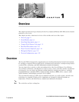
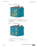
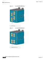
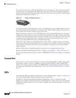
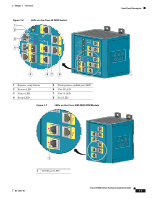
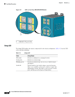
Front-Panel Description Chapter 1 Overview The switch accessory pack includes the mating power and relay connectors. These connectors provide screw terminals for terminating the DC power and alarm wire and the connector plugs into the power and relay receptacles on the front panel. The positive DC power connection is labeled V, and the return connection is labeled RT (see Figure 1-5). Figure 1-5 Power and Relay Connector V RT A A 201815 The switch can operate with a single power source or with dual power sources. When both power sources are operational, the switch draws power from the DC source with the higher voltage. If one of the two power sources fail, the other continues to power the switch. The power and relay connectors also provide an interface for two independent alarm relays: the major and the minor alarms. The relays can be activated for environmental, power supply, and port status alarm conditions and can be configured to indicate an alarm with either open or closed contacts. The relay itself is normally open, so under power failure conditions, the contacts are open. From the CLI, you can associate any alarm condition with one or with both alarm relays. Alarm relays often control an external alarm device, such as a bell or a light. To connect an external alarm device to the relay, you must connect two relay contact wires to complete an electrical circuit. Both alarm terminals on the power and relay connector are labeled A, and you can connect them without regard to polarity. See the switch software configuration guide for instructions on configuring the alarm relays. For more information about the power and relay connector, see Appendix C, "Cable and Connectors." You can get replacement power and relay connectors (PWR-IE3000-CNCT=) by calling Cisco Technical Support. Console Port You can connect a switch to a PC through the console port and the supplied RJ-45-to-DB-9 adapter cable. If you want to connect a switch to a terminal, you need to provide an RJ-45-to-DB-25 female DTE adapter. You can order a kit (part number ACS-DSBUASYN=) with that adapter from Cisco Systems. For console-port and adapter-pinout information, see the "Two Twisted-Pair Cable Pinouts" section on page C-5. LEDs You can use the LEDs to monitor the switch status, activity, and performance. Figure 1-6 to Figure 1-9 show the front panel LEDs, and the following sections describe them. All LEDs are visible through the GUI management applications-the Cisco Network Assistant application for multiple switches and the device manager GUI for a single switch. The switch software configuration guide describes how to use the CLI to configure and to monitor individual switches and switch clusters. Cisco IE 3000 Switch Hardware Installation Guide 1-6 OL-13017-01
-
 1
1 -
2
-
3
-
4
-
5
-
6
-
7
-
8
-
9
-
10
-
 11
11 -
 12
12 -
 13
13 -
 14
14 -
 15
15 -
 16
16 -
 17
17 -
 18
18 -
 19
19 -
 20
20 -
 21
21 -
22
-
23
-
24
-
25
-
26
-
27
-
28
-
29
-
30
-
31
-
32
-
33
-
34
-
35
-
36
-
37
-
38
-
39
-
40
-
41
-
42
-
43
-
44
-
45
-
46
-
47
-
48
-
49
-
50
-
51
-
52
-
53
-
54
-
55
-
56
-
57
-
58
-
59
-
60
-
61
-
62
-
63
-
64
-
65
-
66
-
67
-
68
-
69
-
70
-
71
-
72
-
73
-
74
-
75
-
76
-
77
-
78
-
79
-
80
-
81
-
82
-
83
-
84
-
85
-
86
-
87
-
88
-
89
-
90
-
91
-
92
-
93
-
94
-
95
-
96
-
97
-
98
-
99
-
100
-
101
-
102
-
103
-
104
-
105
-
106
-
107
-
108
-
109
-
110
-
111
-
112
-
113
-
114
-
115
-
116
-
117
-
118
-
119
-
120
-
121
-
122
-
123
-
124
-
125
-
126
-
127
-
128
-
129
-
130
-
131
-
132
-
133
-
134
-
135
-
136
-
137
-
138
-
139
-
140
-
141
-
142
-
143
-
144
-
145
-
146
-
147
-
148
-
149
-
150
-
151
-
152
-
153
-
154
-
155
-
156
-
157
-
158
-
159
-
160
-
161
-
162
-
163
-
164
-
165
-
166
-
167
-
168
-
169
-
170
 |
 |