Cisco IE-3000-4TC Installation Guide - Page 72
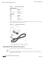
Installing the Power Converter on a DIN Rail, Wall, or Rack Adapter, Connecting the DC Power Clip - express setup
 |
UPC - 882658187797
View all Cisco IE-3000-4TC manuals
Add to My Manuals
Save this manual to your list of manuals |
Page 72 highlights
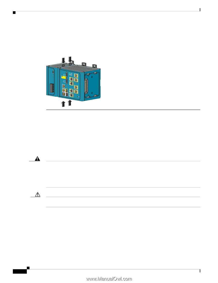
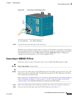
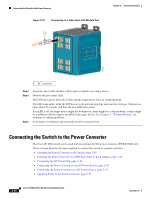
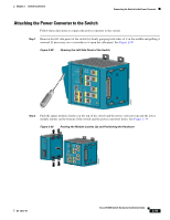
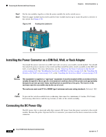
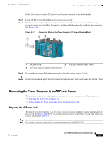
Connecting the Switch to the Power Converter Chapter 2 Switch Installation Step 3 Step 4 Put the two modules together so that the power module fits in the switch recess. Push the upper module latches down and the lower module latches up to secure the power converter to the switch. See Figure 2-40. Figure 2-40 Pushing the Latches In CONSOLE 202297 Pwr A (24VDC or 48 VDC) Rtn A Major Alarm 5 ! WARNING Tpeploohewwicseetrurrinccciotosrmrhddois.gchbkTteohfdoairrsveecedosumnecnroevericecthtintehtghareunisnkotitwn.oeof Pwr B (24VDC or 48 VDC) 1 Rtn B 6 Minor Alarm 2 Express Setup System Pwr A Alarm Pwr B 7 Setup 1 3 8 2 4 Cisco Catalyst Installing the Power Converter on a DIN Rail, Wall, or Rack Adapter You install the power converter on a DIN rail, wall, or rack as you would a switch module. You should first attach the power converter to the switch and then install the entire switch assembly on the DIN rail, wall, or rack adapter. For more information, see the "Attaching the Power Converter to the Switch" section on page 2-45, the "Installing the Switch on a DIN Rail" section on page 2-23, the "Installing the Switch on the Wall" section on page 2-27, or the "Installing the Switch in a Rack" section on page 2-29. Warning This equipment is supplied as "open type" equipment. It must be mounted within an enclosure that is suitably designed for those specific environmental conditions that will be present and appropriately designed to prevent personal injury resulting from accessibility to live parts. The interior of the enclosure must be accessible only by the use of a tool. The enclosure must meet IP 54 or NEMA type 4 minimum enclosure rating standards. Statement 1063 Caution To prevent the switch assemble from overheating, there must be a minimum of 3 inches (76.19 mm) between any other device and the top, bottom, or sides of the switch assembly. Connecting the DC Power Clip The DC power clip is a prewired cable that connects DC power from the power converter to the switch module. Because the power clip uses the Pwr A connector, you cannot use the alarm connections on that connector. 2-46 Cisco IE 3000 Switch Hardware Installation Guide OL-13017-01
-
 1
1 -
2
-
3
-
4
-
5
-
6
-
7
-
8
-
9
-
10
-
11
-
12
-
13
-
14
-
15
-
16
-
17
-
18
-
19
-
20
-
21
-
22
-
23
-
24
-
25
-
26
-
27
-
28
-
29
-
30
-
31
-
32
-
33
-
34
-
35
-
36
-
37
-
38
-
39
-
40
-
41
-
42
-
43
-
44
-
45
-
46
-
47
-
48
-
49
-
50
-
51
-
52
-
53
-
54
-
55
-
56
-
57
-
58
-
59
-
60
-
61
-
62
-
63
-
64
-
65
-
66
-
 67
67 -
 68
68 -
 69
69 -
 70
70 -
 71
71 -
 72
72 -
 73
73 -
 74
74 -
 75
75 -
 76
76 -
 77
77 -
78
-
79
-
80
-
81
-
82
-
83
-
84
-
85
-
86
-
87
-
88
-
89
-
90
-
91
-
92
-
93
-
94
-
95
-
96
-
97
-
98
-
99
-
100
-
101
-
102
-
103
-
104
-
105
-
106
-
107
-
108
-
109
-
110
-
111
-
112
-
113
-
114
-
115
-
116
-
117
-
118
-
119
-
120
-
121
-
122
-
123
-
124
-
125
-
126
-
127
-
128
-
129
-
130
-
131
-
132
-
133
-
134
-
135
-
136
-
137
-
138
-
139
-
140
-
141
-
142
-
143
-
144
-
145
-
146
-
147
-
148
-
149
-
150
-
151
-
152
-
153
-
154
-
155
-
156
-
157
-
158
-
159
-
160
-
161
-
162
-
163
-
164
-
165
-
166
-
167
-
168
-
169
-
170
 |
 |