Cisco IE-3000-4TC Installation Guide - Page 45
Torquing the Power and Relay Connector Captive Screws, Step 4 - dc power terminal
 |
UPC - 882658187797
View all Cisco IE-3000-4TC manuals
Add to My Manuals
Save this manual to your list of manuals |
Page 45 highlights
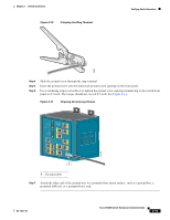
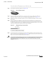
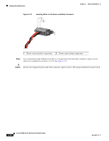
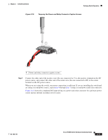
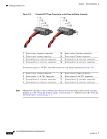
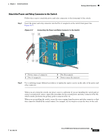
Chapter 2 Switch Installation Verifying Switch Operation Figure 2-15 Torquing the Power and Relay Connector Captive Screws 1 V RT A A 201817 1 Power and relay connector captive screws Step 7 Connect the other end of the positive wire (the one connected to V) to the positive terminal on the DC power source, and connect the other end of the return wire (the one connected to RT) to the return terminal on the DC power source. When you are testing the switch, one power connection is sufficient. If you are installing the switch and are using a second power source, repeat Step 4 through Step 7 using a second power and relay connector. Figure 2-16 shows the completed DC-input wiring on a power and relay connector for a primary power source and an optional secondary power source. OL-13017-01 Cisco IE 3000 Switch Hardware Installation Guide 2-19
-
 1
1 -
2
-
3
-
4
-
5
-
6
-
7
-
8
-
9
-
10
-
11
-
12
-
13
-
14
-
15
-
16
-
17
-
18
-
19
-
20
-
21
-
22
-
23
-
24
-
25
-
26
-
27
-
28
-
29
-
30
-
31
-
32
-
33
-
34
-
35
-
36
-
37
-
38
-
39
-
 40
40 -
 41
41 -
 42
42 -
 43
43 -
 44
44 -
 45
45 -
 46
46 -
 47
47 -
 48
48 -
 49
49 -
 50
50 -
51
-
52
-
53
-
54
-
55
-
56
-
57
-
58
-
59
-
60
-
61
-
62
-
63
-
64
-
65
-
66
-
67
-
68
-
69
-
70
-
71
-
72
-
73
-
74
-
75
-
76
-
77
-
78
-
79
-
80
-
81
-
82
-
83
-
84
-
85
-
86
-
87
-
88
-
89
-
90
-
91
-
92
-
93
-
94
-
95
-
96
-
97
-
98
-
99
-
100
-
101
-
102
-
103
-
104
-
105
-
106
-
107
-
108
-
109
-
110
-
111
-
112
-
113
-
114
-
115
-
116
-
117
-
118
-
119
-
120
-
121
-
122
-
123
-
124
-
125
-
126
-
127
-
128
-
129
-
130
-
131
-
132
-
133
-
134
-
135
-
136
-
137
-
138
-
139
-
140
-
141
-
142
-
143
-
144
-
145
-
146
-
147
-
148
-
149
-
150
-
151
-
152
-
153
-
154
-
155
-
156
-
157
-
158
-
159
-
160
-
161
-
162
-
163
-
164
-
165
-
166
-
167
-
168
-
169
-
170
 |
 |
