Cisco IE-3000-4TC Installation Guide - Page 68
Connecting to a Dual-Purpose Port - sfp
 |
UPC - 882658187797
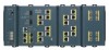
View all Cisco IE-3000-4TC manuals
Add to My Manuals
Save this manual to your list of manuals |
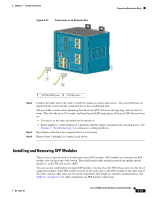
Page 68 highlights
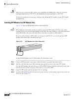
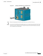
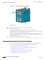
Connecting Destination Ports Chapter 2 Switch Installation Step 5 The LED turns amber while the STP discovers the network topology and searches for loops. This process takes about 30 seconds, and then the port LED turns green. If the LED is off, the target device might not be turned on, there might be a cable problem, or there might be a problem with the adapter installed in the target device. See Chapter 3, "Troubleshooting," for solutions to cabling problems. If necessary, reconfigure and restart the switch or the target device. Connecting to a Dual-Purpose Port The dual-purpose port is a single port with two interfaces, one for an RJ-45 cable and another for an SFP module. Only one interface can be active at a time. If both interfaces are connected, the SFP module has priority. For more information about dual-purpose ports, see the "Dual-Purpose Ports" section on page 1-5. Warning Class 1 laser product. Statement 1008 Caution Do not remove the rubber plugs from the SFP module port or the rubber caps from the fiber-optic cable until you are ready to connect the cable. The plugs and caps protect the SFP module ports and cables from contamination and ambient light. Before connecting to the SFP module, be sure that you understand the port and cabling stipulations in the "Preparing for Installation" section on page 2-1. See Appendix C, "Cable and Connectors," for information about the LC on the SFP module. To connect to a dual-purpose port, follow these steps: Step 1 Connect an RJ-45 connector to the 10/100/1000 port, or install an SFP module into the SFP module slot, and connect a cable to the SFP module port. See Figure 2-36. For more information about RJ-45 connections, SFP modules, and optical connections, see the "Connecting to 10/100 and 10/100/1000 Ports" section on page 2-36, the "Installing and Removing SFP Modules" section on page 2-37, and the "Connecting to SFP Modules" section on page 2-41. 2-42 Cisco IE 3000 Switch Hardware Installation Guide OL-13017-01
-
 1
1 -
2
-
3
-
4
-
5
-
6
-
7
-
8
-
9
-
10
-
11
-
12
-
13
-
14
-
15
-
16
-
17
-
18
-
19
-
20
-
21
-
22
-
23
-
24
-
25
-
26
-
27
-
28
-
29
-
30
-
31
-
32
-
33
-
34
-
35
-
36
-
37
-
38
-
39
-
40
-
41
-
42
-
43
-
44
-
45
-
46
-
47
-
48
-
49
-
50
-
51
-
52
-
53
-
54
-
55
-
56
-
57
-
58
-
59
-
60
-
61
-
62
-
 63
63 -
 64
64 -
 65
65 -
 66
66 -
 67
67 -
 68
68 -
 69
69 -
 70
70 -
 71
71 -
 72
72 -
 73
73 -
74
-
75
-
76
-
77
-
78
-
79
-
80
-
81
-
82
-
83
-
84
-
85
-
86
-
87
-
88
-
89
-
90
-
91
-
92
-
93
-
94
-
95
-
96
-
97
-
98
-
99
-
100
-
101
-
102
-
103
-
104
-
105
-
106
-
107
-
108
-
109
-
110
-
111
-
112
-
113
-
114
-
115
-
116
-
117
-
118
-
119
-
120
-
121
-
122
-
123
-
124
-
125
-
126
-
127
-
128
-
129
-
130
-
131
-
132
-
133
-
134
-
135
-
136
-
137
-
138
-
139
-
140
-
141
-
142
-
143
-
144
-
145
-
146
-
147
-
148
-
149
-
150
-
151
-
152
-
153
-
154
-
155
-
156
-
157
-
158
-
159
-
160
-
161
-
162
-
163
-
164
-
165
-
166
-
167
-
168
-
169
-
170
 |
 |
