Cisco SGE2010 Administration Guide - Page 10
Wall-Mount Placement, Connecting the Cables - mini gbic cables
 |
UPC - 745883581269
View all Cisco SGE2010 manuals
Add to My Manuals
Save this manual to your list of manuals |
Page 10 highlights
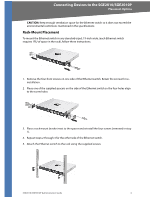
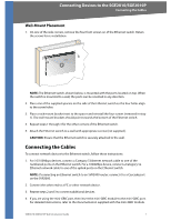
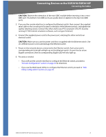
Connecting Devices to the SGE2010/SGE2010P Connecting the Cables Wall-Mount Placement 1. On one of the side corners, remove the four front screws on of the Ethernet switch. Retain the screws for re-installation. NOTE: The Ethernet switch, shown below, is mounted with the ports located on top. When the switch is mounted to a wall, the ports can be oriented in any direction. 2. Place one of the supplied spacers on the side of the Ethernet switch so the four holes align to the screw holes. 3. Place a rack mount bracket next to the spacer and reinstall the four screws (removed in step 1). The wall mount brackets should point towards the bottom of the Ethernet switch. 4. Repeat steps 1 through 3 for the other corners of the Ethernet switch. 5. Attach the Ethernet switch to a wall with appropriate screws (not supplied). CAUTION: Ensure that the Ethernet switch is securely attached to the wall. Connecting the Cables To connect network devices to the Ethernet switch, follow these instructions: 1. For 10/100Mbps devices, connect a Category 5 Ethernet network cable to one of the numbered ports on the Ethernet switch. For a 1000Mbps device, connect a Category 5e Ethernet network cable to one of the uplink ports on the Ethernet switch. NOTE: If connecting an Ethernet switch to an SVR3000 router, connect it to a Cascade port on the SVR3000. 2. Connect the other end to a PC or other network device. 3. Repeat steps 2 and 3 to connect additional devices. 4. If you are using the mini-GBIC port, then insert the mini-GBIC module to the mini-GBIC port. For detailed instructions, refer to the documentation supplied with the mini-GBIC module. SGE2010/SGE2010P Administration Guide 7
-
 1
1 -
2
-
3
-
4
-
 5
5 -
 6
6 -
 7
7 -
 8
8 -
 9
9 -
 10
10 -
 11
11 -
 12
12 -
 13
13 -
 14
14 -
 15
15 -
16
-
17
-
18
-
19
-
20
-
21
-
22
-
23
-
24
-
25
-
26
-
27
-
28
-
29
-
30
-
31
-
32
-
33
-
34
-
35
-
36
-
37
-
38
-
39
-
40
-
41
-
42
-
43
-
44
-
45
-
46
-
47
-
48
-
49
-
50
-
51
-
52
-
53
-
54
-
55
-
56
-
57
-
58
-
59
-
60
-
61
-
62
-
63
-
64
-
65
-
66
 |
 |
