Cisco SGE2010 Administration Guide - Page 9
Rack-Mount Placement
 |
UPC - 745883581269
View all Cisco SGE2010 manuals
Add to My Manuals
Save this manual to your list of manuals |
Page 9 highlights
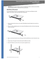
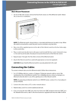
Connecting Devices to the SGE2010/SGE2010P Placement Options CAUTION: Keep enough ventilation space for the Ethernet switch so it does not exceed the environmental restrictions mentioned in the specifications. Rack-Mount Placement To mount the Ethernet switch in any standard-sized, 19-inch wide, (each Ethernet switch requires 1RU of space in the rack), follow these instructions: 1. Remove the four front screws on one side of the Ethernet switch. Retain the screws for reinstallation. 2. Place one of the supplied spacers on the side of the Ethernet switch so the four holes align to the screw holes. 3. Place a rack mount bracket next to the spacer and reinstall the four screws (removed in step 1). 4. Repeat steps 2 through 3 for the other side of the Ethernet switch. 5. Attach the Ethernet switch to the rack using the supplied screws. SGE2010/SGE2010P Administration Guide 6
-
 1
1 -
2
-
3
-
 4
4 -
 5
5 -
 6
6 -
 7
7 -
 8
8 -
 9
9 -
 10
10 -
 11
11 -
 12
12 -
 13
13 -
 14
14 -
15
-
16
-
17
-
18
-
19
-
20
-
21
-
22
-
23
-
24
-
25
-
26
-
27
-
28
-
29
-
30
-
31
-
32
-
33
-
34
-
35
-
36
-
37
-
38
-
39
-
40
-
41
-
42
-
43
-
44
-
45
-
46
-
47
-
48
-
49
-
50
-
51
-
52
-
53
-
54
-
55
-
56
-
57
-
58
-
59
-
60
-
61
-
62
-
63
-
64
-
65
-
66
 |
 |
