Cisco UBR904 Troubleshooting Guide - Page 19
show controllers cable-modem, Table 2, Show Controllers Cable-Modem Field Descriptions, Field
 |
View all Cisco UBR904 manuals
Add to My Manuals
Save this manual to your list of manuals |
Page 19 highlights
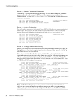
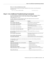
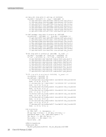
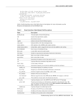
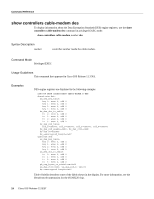
show controllers cable-modem ds_data_dma_ctrl=0x98, ds_mac_dma_ctrl=0xD8 ds_dma_data_index=0x0007, ds_dma_msg_index=0x0000 upstream dma: us_bd_base=0x001FB8, us_pd_base=0x002038 us_dma_ctrl=0x80, us_dma_tx_start=0x00 Global control and status: global_ctrl_status=0x00 interrupts: irq_pend=0x0008, irq_mask=0x00F7 Table 2 briefly describes some of the fields shown in the display. For more information, see the Broadcom documentation for the BCM3220 chip. Table 2 Show Controllers Cable-Modem Field Descriptions Field BCM3220 unit idb ds regaddr reset_mask station address default station address PLD VERSION MAC state Prev States MAC mcfilter data mcfilter DS US Tuner: status Rx: tuner_freq symbol_rate local_freq snr_estimate ber_estimate lock_threshold qam_mode Tx: tx_freq power_level symbol_rate TFTP server TOD server Security server Description The unit number of this BCM3220 chip. Interface description block number. Downstream channel. Indicates the start of the BCM3220 registers. Indicates the bit to hit when resetting the chip. MAC address of this uBR904 cable modem interface. Default MAC address assigned by the factory for this uBR904 cable modem. PLD version of the BCM3220 chip. Current MAC state of the cable modem. Number of states that have previously existed since initialization. MAC control filter for MAC messages. MAC control filter for data. Downstream Broadcom receiver chip number and ID. Upstream Broadcom transmitter chip number and ID. Current status of the tuner. Downstream frequency (in Hz) that the uBR904 searched for and found. Downstream frequency in symbols per second. Frequency on which the transmitter and the tuner communicate. Estimate of signal-to-noise ratio (SNR) in Db X 1000. Estimate of bit error rate (always 0). Minimum signal-to-noise ratio (SNR) that the uBR904 will accept as a valid lock. The modulation scheme used in the downstream direction. Upstream frequency sent to the uBR904 by the CMTS in the UCD message. Transmit power level as set in the hardware, expressed as a hexadecimal value. The units are unique to the hardware used. Use the show controllers cable-modem 0 mac state command to see the power level in dBmV. Upstream frequency in symbols per second. IP address of the TFTP server at the headend. IP address of the time-of-day server at the headend. IP address of the security server at the headend. Troubleshooting Tips for the Cisco uBR904 Cable Modem 19
-
 1
1 -
2
-
3
-
4
-
5
-
6
-
7
-
8
-
9
-
10
-
11
-
12
-
13
-
 14
14 -
 15
15 -
 16
16 -
 17
17 -
 18
18 -
 19
19 -
 20
20 -
 21
21 -
 22
22 -
 23
23 -
 24
24 -
25
-
26
-
27
-
28
-
29
-
30
-
31
-
32
-
33
-
34
-
35
-
36
-
37
-
38
-
39
-
40
-
41
-
42
-
43
-
44
-
45
-
46
-
47
-
48
-
49
-
50
-
51
-
52
-
53
-
54
-
55
-
56
-
57
-
58
-
59
-
60
-
61
-
62
 |
 |