Cisco UBR904 Troubleshooting Guide - Page 42
Command Reference, Table 8, Show Controllers Cable-Modem, MAC State Field Descriptions Continued
 |
View all Cisco UBR904 manuals
Add to My Manuals
Save this manual to your list of manuals |
Page 42 highlights
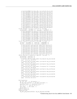
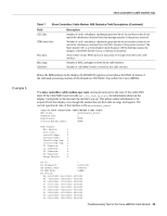
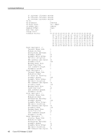
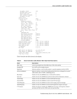
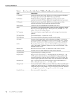
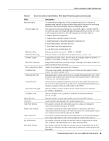
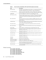
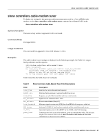
Command Reference Table 8 Show Controllers Cable-Modem MAC State Field Descriptions (Continued) Field T2 Timeouts T3 Timeouts T4 Timeouts Range Aborts DS ID DS Frequency DS Symbol Rate DS QAM Mode DS Search US ID US Frequency US Power Level US Symbol Rate Ranging Offset Mini-Slot Size Change Count Preamble Pattern Description Number of timeouts caused by the uBR904 not receiving a maintenance broadcast for ranging opportunities from the CMTS within a specified time. Number of timeouts caused by the uBR904 not receiving a response within a specified time from the CMTS to a RNG-REQ message during initial maintenance. Number of timeouts caused by the uBR904 not receiving a response within a specified time from the CMTS to a periodic maintenance request. Number of times the ranging process was aborted by the CMTS. The identifier of the downstream channel on which this MAC management message has been transmitted. This identifier is arbitrarily chosen by the CMTS and is only unique within the MAC-sublayer domain. Downstream frequency acquired by the cable modem during its last initialization sequence. Downstream frequency in symbols per second. Downstream modulation scheme being used by the cable modem. Frequency bands scanned by the cable modem when searching for a downstream channel. The uBR904's default frequency bands correspond to the North American EIA CATV channel plan for 6 MHz channel slots between 90 MHz and 858 MHz. The identifier of the upstream channel to which this MAC management message refers. This identifier is arbitrarily chosen by the CMTS and is only unique within the MAC-sublayer domain. Transmission frequency used by the cable modem in the upstream direction. Transmit power level of the cable modem in the upstream direction. Upstream frequency in symbols per second. Delay correction (in increments of 6.25 us/64) applied by the cable modem to the CMTS upstream frame time derived at the cable modem. Used to synchronize the upstream transmissions in the time division multiple access (TDMA) scheme, this value is roughly equal to the round-trip delay of the cable modem from the CMTS. Size T of the mini-slot for this upstream channel in units of the timebase tick of 6.25 us. Allowable values are 2, 4, 8, 16, 32, 64, or 128. Incremented by 1 by the CMTS whenever any of the values of this channel descriptor change. If the value of this count in a sebsequent upstream channel descriptor (UCD) remains the same, the cable modem can quickly decide that the remaining fields have not changed, and may be able to disregard the remainder of the message. Byte pattern used for the preamble. 42 Cisco IOS Release 12.0(3)T
-
 1
1 -
2
-
3
-
4
-
5
-
6
-
7
-
8
-
9
-
10
-
11
-
12
-
13
-
14
-
15
-
16
-
17
-
18
-
19
-
20
-
21
-
22
-
23
-
24
-
25
-
26
-
27
-
28
-
29
-
30
-
31
-
32
-
33
-
34
-
35
-
36
-
 37
37 -
 38
38 -
 39
39 -
 40
40 -
 41
41 -
 42
42 -
 43
43 -
 44
44 -
 45
45 -
 46
46 -
 47
47 -
48
-
49
-
50
-
51
-
52
-
53
-
54
-
55
-
56
-
57
-
58
-
59
-
60
-
61
-
62
 |
 |