Cisco WAE-674-K9 Hardware Installation Guide - Page 17
Front Panel Controls and LEDs - diagnostics
 |
UPC - 882658200076
View all Cisco WAE-674-K9 manuals
Add to My Manuals
Save this manual to your list of manuals |
Page 17 highlights
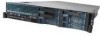
Chapter 1 Introducing the Cisco Wide Area Application Engine Hardware Features Front Panel Controls and LEDs Figure 1-1 shows the front panel controls and LEDs. Figure 1-1 Front Panel Operator information panel (note expanded view) Hard disk drive activity LED (green) USB 5 connector USB 6 connector Video connector Hard disk drive status LED (amber) OL-15012-02 CD/DVD eject button CD/DVD drive activity LED Rack release latch Rack release latch Hard disk drive activity LED Information Release LED latch Operator information panel (expanded view) 185083 Power-control Power-on button LED Systemlocator LED System-error LED The power control button powers up and powers down the system. A power control button shield prevents the system from being powered down accidentally. On the operator information panel, slide the release latch to the left to access the Light Path Diagnostics panel, which is behind the operator information panel. For more information on Light Path Diagnostics, see the "Identifying Problems Using Trouble Indicators and Status LEDs" section on page 6-15. Cisco Wide Area Application Engine 7341, 7371, and 674 Hardware Installation Guide 1-3
-
 1
1 -
2
-
3
-
4
-
5
-
6
-
7
-
8
-
9
-
10
-
11
-
 12
12 -
 13
13 -
 14
14 -
 15
15 -
 16
16 -
 17
17 -
 18
18 -
 19
19 -
 20
20 -
 21
21 -
 22
22 -
23
-
24
-
25
-
26
-
27
-
28
-
29
-
30
-
31
-
32
-
33
-
34
-
35
-
36
-
37
-
38
-
39
-
40
-
41
-
42
-
43
-
44
-
45
-
46
-
47
-
48
-
49
-
50
-
51
-
52
-
53
-
54
-
55
-
56
-
57
-
58
-
59
-
60
-
61
-
62
-
63
-
64
-
65
-
66
-
67
-
68
-
69
-
70
-
71
-
72
-
73
-
74
-
75
-
76
-
77
-
78
-
79
-
80
-
81
-
82
-
83
-
84
-
85
-
86
-
87
-
88
-
89
-
90
-
91
-
92
-
93
-
94
-
95
-
96
-
97
-
98
-
99
-
100
-
101
-
102
-
103
-
104
-
105
-
106
-
107
-
108
-
109
-
110
-
111
-
112
-
113
-
114
-
115
-
116
-
117
-
118
-
119
-
120
-
121
-
122
-
123
-
124
-
125
-
126
-
127
-
128
-
129
-
130
-
131
-
132
-
133
-
134
-
135
-
136
-
137
-
138
-
139
-
140
-
141
-
142
-
143
-
144
-
145
-
146
-
147
-
148
-
149
-
150
-
151
-
152
 |
 |
