Cisco WS-C2950-24 Hardware Installation Guide - Page 109
DC Power Connections for Cisco 3925 and 3925-NOVPN Routers
 |
View all Cisco WS-C2950-24 manuals
Add to My Manuals
Save this manual to your list of manuals |
Page 109 highlights
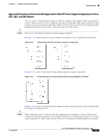
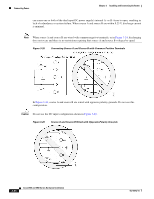
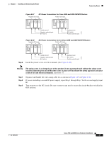
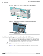
Chapter 3 Installing and Connecting the Router Connecting Power Figure 3-27 DC Power Connections for Cisco 3925 and 3925-NOVPN Routers Negative DC input + PE Positive DC input + PE 279995 Safety ground Negative polarity input 0V (return) Safety ground 0V (return) Positive polarity input Figure 3-28 DC Power Connections for the Cisco 3945 and 3945-NOVPN Routers Negative DC input Positive DC input + PE + PE 279995 Step 6 Safety ground Negative polarity input 0V (return) Safety ground 0V (return) Positive polarity input Install the plastic cover over the terminals. (See Figure 3-29.) Warning The safety cover is an integral part of the product. Do not operate the unit without the safety cover installed. Operating the unit without the cover in place will invalidate the safety approvals and pose a risk of fire and electrical hazards. Statement 117 Step 7 Step 8 Step 9 Organize and bundle the wires using cable ties as shown in Figure 3-29 or Figure 3-30. If you are installing a second DC power supply, repeat Step 1 through Step 7 for the second supply (input B). Turn on power to the DC circuit. Be sure to remove tape used to secure the circuit-breaker switch in the OFF position. OL-18712-01 Cisco 2900 and 3900 Series Hardware Installation 3-27
-
 1
1 -
2
-
3
-
4
-
5
-
6
-
7
-
8
-
9
-
10
-
11
-
12
-
13
-
14
-
15
-
16
-
17
-
18
-
19
-
20
-
21
-
22
-
23
-
24
-
25
-
26
-
27
-
28
-
29
-
30
-
31
-
32
-
33
-
34
-
35
-
36
-
37
-
38
-
39
-
40
-
41
-
42
-
43
-
44
-
45
-
46
-
47
-
48
-
49
-
50
-
51
-
52
-
53
-
54
-
55
-
56
-
57
-
58
-
59
-
60
-
61
-
62
-
63
-
64
-
65
-
66
-
67
-
68
-
69
-
70
-
71
-
72
-
73
-
74
-
75
-
76
-
77
-
78
-
79
-
80
-
81
-
82
-
83
-
84
-
85
-
86
-
87
-
88
-
89
-
90
-
91
-
92
-
93
-
94
-
95
-
96
-
97
-
98
-
99
-
100
-
101
-
102
-
103
-
 104
104 -
 105
105 -
 106
106 -
 107
107 -
 108
108 -
 109
109 -
 110
110 -
 111
111 -
 112
112 -
 113
113 -
 114
114 -
115
-
116
-
117
-
118
-
119
-
120
-
121
-
122
-
123
-
124
-
125
-
126
-
127
-
128
-
129
-
130
-
131
-
132
-
133
-
134
-
135
-
136
-
137
-
138
-
139
-
140
-
141
-
142
-
143
-
144
-
145
-
146
-
147
-
148
-
149
-
150
-
151
-
152
-
153
-
154
-
155
-
156
-
157
-
158
-
159
-
160
-
161
-
162
-
163
-
164
-
165
-
166
-
167
-
168
-
169
-
170
-
171
-
172
-
173
-
174
-
175
-
176
-
177
-
178
-
179
-
180
-
181
-
182
-
183
-
184
-
185
-
186
-
187
-
188
-
189
-
190
-
191
-
192
-
193
-
194
-
195
-
196
-
197
-
198
-
199
-
200
-
201
-
202
-
203
-
204
-
205
-
206
-
207
-
208
-
209
-
210
-
211
-
212
-
213
-
214
-
215
-
216
-
217
-
218
-
219
-
220
 |
 |
