Cisco WS-C2950-24 Hardware Installation Guide - Page 121
Connecting to the Auxiliary Port
 |
View all Cisco WS-C2950-24 manuals
Add to My Manuals
Save this manual to your list of manuals |
Page 121 highlights
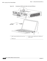
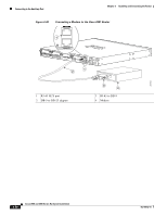
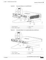
Chapter 3 Installing and Connecting the Router Connecting to the Auxiliary Port Note Disconnect the router console terminal before uninstalling the driver. Step 1 Step 2 Step 3 Step 4 Run the setup.exe for Windows 32-bit or setup(x64).exe for Windows-64bit. Click Next. The InstallShield Wizard for Cisco Virtual Com appears. Click Next. When the Program Maintenance window appears, select the Remove radio button. Click Next. When the Remove the Program window appears, click Remove. Note If a User Account Control warning appears, click "Allow - I trust this program..." to proceed. Step 5 When the InstallShield Wizard Completed window appears click Finish. Connecting to the Auxiliary Port When a modem is connected to the auxiliary port, a remote user can dial in to the router and configure it. Use the light blue console cable and the DB-9-to-DB-25 connector adapter that came in the router accessory kit. To connect a modem to the router, follow these steps: Step 1 Connect the RJ-45 end of the adapter cable to the black AUX port on the router. (See Figure 3-38, Figure 3-39, or Figure 3-40.) OL-18712-01 Cisco 2900 and 3900 Series Hardware Installation 3-39
-
 1
1 -
2
-
3
-
4
-
5
-
6
-
7
-
8
-
9
-
10
-
11
-
12
-
13
-
14
-
15
-
16
-
17
-
18
-
19
-
20
-
21
-
22
-
23
-
24
-
25
-
26
-
27
-
28
-
29
-
30
-
31
-
32
-
33
-
34
-
35
-
36
-
37
-
38
-
39
-
40
-
41
-
42
-
43
-
44
-
45
-
46
-
47
-
48
-
49
-
50
-
51
-
52
-
53
-
54
-
55
-
56
-
57
-
58
-
59
-
60
-
61
-
62
-
63
-
64
-
65
-
66
-
67
-
68
-
69
-
70
-
71
-
72
-
73
-
74
-
75
-
76
-
77
-
78
-
79
-
80
-
81
-
82
-
83
-
84
-
85
-
86
-
87
-
88
-
89
-
90
-
91
-
92
-
93
-
94
-
95
-
96
-
97
-
98
-
99
-
100
-
101
-
102
-
103
-
104
-
105
-
106
-
107
-
108
-
109
-
110
-
111
-
112
-
113
-
114
-
115
-
 116
116 -
 117
117 -
 118
118 -
 119
119 -
 120
120 -
 121
121 -
 122
122 -
 123
123 -
 124
124 -
 125
125 -
 126
126 -
127
-
128
-
129
-
130
-
131
-
132
-
133
-
134
-
135
-
136
-
137
-
138
-
139
-
140
-
141
-
142
-
143
-
144
-
145
-
146
-
147
-
148
-
149
-
150
-
151
-
152
-
153
-
154
-
155
-
156
-
157
-
158
-
159
-
160
-
161
-
162
-
163
-
164
-
165
-
166
-
167
-
168
-
169
-
170
-
171
-
172
-
173
-
174
-
175
-
176
-
177
-
178
-
179
-
180
-
181
-
182
-
183
-
184
-
185
-
186
-
187
-
188
-
189
-
190
-
191
-
192
-
193
-
194
-
195
-
196
-
197
-
198
-
199
-
200
-
201
-
202
-
203
-
204
-
205
-
206
-
207
-
208
-
209
-
210
-
211
-
212
-
213
-
214
-
215
-
216
-
217
-
218
-
219
-
220
 |
 |
