Cisco WS-C2950-24 Hardware Installation Guide - Page 195
Installing an RPS Adapter, Removing an RPS Adapter
 |
View all Cisco WS-C2950-24 manuals
Add to My Manuals
Save this manual to your list of manuals |
Page 195 highlights
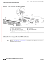
Chapter 5 Installing and Upgrading Internal Modules and FRUs Replacing Power Supplies and Redundant Power Supplies Table 5-3 RPS 2300 Backup Capabilities (continued) Power Mode 2911 in POE Boost 2921, 2951 in POE Boost Quantity and Type of RPS 2300 FRU Quantity 1 Quantity 2 Quantity 1 Quantity 2 C3K-PWR-750WAC C3K-PWR-750WAC C3K-PWR-1150WAC C3K-PWR-1150WAC 0 1 1 2 0 1 0 1 Installing an RPS Adapter To install an RPS adapter, perform the following steps: Caution The RPS adapter must be in the router chassis before connecting to the RPS. Step 1 Step 2 Step 3 Step 4 Step 5 Step 6 Step 7 Step 8 Step 9 Read the "Safety Warnings" section on page 5-2 section and disconnect the power supply before you perform any module replacement. Ensure AC or DC power is disconnected from the router power supply. If connected, place the RPS 2300 into standby mode. Consult the Cisco Redundant Power System 2300 Hardware Installation Guide for operating the RPS 2300. If an RPS Adapter had never been installed, a blank panel is in its place. Remove the RPS Adapter blank panel. Insert the RPS adapter into the router (Figure 5-29 or Figure 5-30) and tighten the screws. Connect the RPS 2300 cable into the RPS adapter connector. Connect the other end of the RPS 2300 cable to the RPS 2300. Power up the router. Place the RPS into Active mode. Removing an RPS Adapter To remove an RPS adapter, perform the following steps: Step 1 Step 2 Step 3 Step 4 Step 5 Step 6 Read the Safety Warnings section and disconnect the power supply before you perform any module replacement. If connected, place the RPS 2300 into standby mode. Consult the Cisco Redundant Power System 2300 Hardware Installation Guide for operating the RPS 2300. Power off and disconnect the AC or DC power from the router power supply. Remove the RPS cable from the RPS 2300. Remove the other end of the RPS 2300 cable from the RPS adapter. Remove the RPS adapter. OL-18712-03 Cisco 2900 Series and 3900 Series Hardware Installation Guide 5-43
-
 1
1 -
2
-
3
-
4
-
5
-
6
-
7
-
8
-
9
-
10
-
11
-
12
-
13
-
14
-
15
-
16
-
17
-
18
-
19
-
20
-
21
-
22
-
23
-
24
-
25
-
26
-
27
-
28
-
29
-
30
-
31
-
32
-
33
-
34
-
35
-
36
-
37
-
38
-
39
-
40
-
41
-
42
-
43
-
44
-
45
-
46
-
47
-
48
-
49
-
50
-
51
-
52
-
53
-
54
-
55
-
56
-
57
-
58
-
59
-
60
-
61
-
62
-
63
-
64
-
65
-
66
-
67
-
68
-
69
-
70
-
71
-
72
-
73
-
74
-
75
-
76
-
77
-
78
-
79
-
80
-
81
-
82
-
83
-
84
-
85
-
86
-
87
-
88
-
89
-
90
-
91
-
92
-
93
-
94
-
95
-
96
-
97
-
98
-
99
-
100
-
101
-
102
-
103
-
104
-
105
-
106
-
107
-
108
-
109
-
110
-
111
-
112
-
113
-
114
-
115
-
116
-
117
-
118
-
119
-
120
-
121
-
122
-
123
-
124
-
125
-
126
-
127
-
128
-
129
-
130
-
131
-
132
-
133
-
134
-
135
-
136
-
137
-
138
-
139
-
140
-
141
-
142
-
143
-
144
-
145
-
146
-
147
-
148
-
149
-
150
-
151
-
152
-
153
-
154
-
155
-
156
-
157
-
158
-
159
-
160
-
161
-
162
-
163
-
164
-
165
-
166
-
167
-
168
-
169
-
170
-
171
-
172
-
173
-
174
-
175
-
176
-
177
-
178
-
179
-
180
-
181
-
182
-
183
-
184
-
185
-
186
-
187
-
188
-
189
-
 190
190 -
 191
191 -
 192
192 -
 193
193 -
 194
194 -
 195
195 -
 196
196 -
 197
197 -
 198
198 -
 199
199 -
 200
200 -
201
-
202
-
203
-
204
-
205
-
206
-
207
-
208
-
209
-
210
-
211
-
212
-
213
-
214
-
215
-
216
-
217
-
218
-
219
-
220
 |
 |
