Cisco WS-C2950-24 Hardware Installation Guide - Page 28
Cisco 3900 Series Chassis, Router, Services Performance Engine
 |
View all Cisco WS-C2950-24 manuals
Add to My Manuals
Save this manual to your list of manuals |
Page 28 highlights
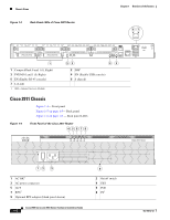
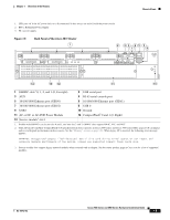
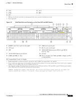
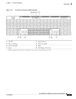
Chassis Views Figure 1-9 Back Panel LEDS of the Cisco 2921 and 2951 Routers Chapter 1 Overview of the Routers 8 9 250901 EHWIC 3 EHWIC 2 EHWIC 1 DO NOT REMOVE DURING NETWORKING OPERATION CF 1 DO NOT RNEDMEOOTVNWEOODTURRRKINEIGNMGNOEOTVWEPOEDRRKUIANRTGIINOOGPNERATION CF 0 ISM PVDM2 PVDM1 PVDM0 EHWIC 0 EN AUX SFP E N EN S CONSOLE GE 0/2 S S G L E 0 / 0 1 USB 0 GE 0/1 1 2 3 4 5 67 1 CompactFlash 0 and 1 (0, Right) 3 PVDM3 0,1, and 2 (0, Right) 5 EN (Enable RJ-45 console) 7 SFP S 9 L (Link) 1. ISM = Internal Services Module 2. SFP = small-form-factor pluggable 2 ISM1 4 EN (Enable USB console) 6 SFP2 EN 8 S (Speed) L 2921 SM SLOT 1 Cisco 3900 Series Chassis Cisco 3900 series ISRs are shipped with Services Performance Engines (SPEs) pre-installed in the router. See the "Services Performance Engine" section on page 1-20 for models and support information. Table 1-2 Services Performance Engines Router Cisco 3925 Cisco 3945 Cisco 3925E Cisco 3945E Services Performance Engine Services Performance Engine 100 Services Performance Engine 150 Services Performance Engine 200 Services Performance Engine 250 Figure 1-10 shows the Cisco 3925 and Cisco 3945 front panels. Cisco 3925 and Cisco 3945 (SPE 100 and SPE 150) • Back panel slots and connectors- Figure 1-11 • Back panel LEDs- Figure 1-12 Cisco 3925E and Cisco 3945E (SPE 200 or SPE 250) • Back panel slots and connectors- Figure 1-13 • Back panel LEDs- Figure 1-14 Cisco 2900 Series and 3900 Series Hardware Installation Guide 1-8 OL-18712-02
-
 1
1 -
2
-
3
-
4
-
5
-
6
-
7
-
8
-
9
-
10
-
11
-
12
-
13
-
14
-
15
-
16
-
17
-
18
-
19
-
20
-
21
-
22
-
 23
23 -
 24
24 -
 25
25 -
 26
26 -
 27
27 -
 28
28 -
 29
29 -
 30
30 -
 31
31 -
 32
32 -
 33
33 -
34
-
35
-
36
-
37
-
38
-
39
-
40
-
41
-
42
-
43
-
44
-
45
-
46
-
47
-
48
-
49
-
50
-
51
-
52
-
53
-
54
-
55
-
56
-
57
-
58
-
59
-
60
-
61
-
62
-
63
-
64
-
65
-
66
-
67
-
68
-
69
-
70
-
71
-
72
-
73
-
74
-
75
-
76
-
77
-
78
-
79
-
80
-
81
-
82
-
83
-
84
-
85
-
86
-
87
-
88
-
89
-
90
-
91
-
92
-
93
-
94
-
95
-
96
-
97
-
98
-
99
-
100
-
101
-
102
-
103
-
104
-
105
-
106
-
107
-
108
-
109
-
110
-
111
-
112
-
113
-
114
-
115
-
116
-
117
-
118
-
119
-
120
-
121
-
122
-
123
-
124
-
125
-
126
-
127
-
128
-
129
-
130
-
131
-
132
-
133
-
134
-
135
-
136
-
137
-
138
-
139
-
140
-
141
-
142
-
143
-
144
-
145
-
146
-
147
-
148
-
149
-
150
-
151
-
152
-
153
-
154
-
155
-
156
-
157
-
158
-
159
-
160
-
161
-
162
-
163
-
164
-
165
-
166
-
167
-
168
-
169
-
170
-
171
-
172
-
173
-
174
-
175
-
176
-
177
-
178
-
179
-
180
-
181
-
182
-
183
-
184
-
185
-
186
-
187
-
188
-
189
-
190
-
191
-
192
-
193
-
194
-
195
-
196
-
197
-
198
-
199
-
200
-
201
-
202
-
203
-
204
-
205
-
206
-
207
-
208
-
209
-
210
-
211
-
212
-
213
-
214
-
215
-
216
-
217
-
218
-
219
-
220
 |
 |
