Cisco WS-C2950-24 Hardware Installation Guide - Page 113
Connecting to Backup Power, Connecting to a Console Terminal or Modem
 |
View all Cisco WS-C2950-24 manuals
Add to My Manuals
Save this manual to your list of manuals |
Page 113 highlights
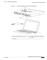
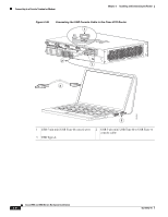
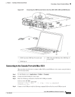
Chapter 3 Installing and Connecting the Router Connecting to a Console Terminal or Modem Connecting to Backup Power The redundant power supply (RPS) for the Cisco 2911, Cisco 2921, and Cisco 2951 router is an external Cisco RPS 2300. To connect the RPS, the router must be fitted with an RPS adapter. See the "Installing and Removing a Redundant Power Supply Adapter" section on page 5-42 before connecting to a backup power source. If your router uses the Cisco Redundant Power System (RPS), see the Cisco Redundant Power System 2300 Hardware Installation Guide for instructions about the power connections. You can access this document at: http://www.cisco.com/en/US/docs/switches/power_supplies/rps2300/hardware/installation/guide/2300 hig.html Caution Before connecting the RPS to the router, make sure that either the RPS is in standby mode or the RPS AC power is disconnected. Connecting the RPS to AC power automatically places the RPS in active mode. Note The Cisco 2901 router does not support an RPS. Connecting to a Console Terminal or Modem The router has asynchronous serial ports and auxiliary ports. These ports provide administrative access to the router either locally (with a console terminal or a PC) or remotely (with a modem).To configure the router through the Cisco IOS CLI, you must establish a connection between the router console port and either a terminal or a PC. Use the following cables and adapters to establish a local or remote connection. Table 3-4 Local and Remote Connections Port Type Cable Serial (RJ-45) EIA RJ-45 Serial (USB) USB 5-pin mini USB Type-B-to-USB Type-A Auxiliary (Modem) DB-9-to-DB-25 Section Connecting to the Serial Port with Microsoft Windows Connecting to the Auxiliary Port Connecting to the Serial Port with Microsoft Windows Note Install the USB device driver before establishing a physical connection between the router and the PC using the USB Console cable plugged into the USB serial port, otherwise the connection will fail. See the "Installing the Cisco Microsoft Windows USB Device Driver" section on page 3-36. OL-18712-01 Cisco 2900 and 3900 Series Hardware Installation 3-31
-
 1
1 -
2
-
3
-
4
-
5
-
6
-
7
-
8
-
9
-
10
-
11
-
12
-
13
-
14
-
15
-
16
-
17
-
18
-
19
-
20
-
21
-
22
-
23
-
24
-
25
-
26
-
27
-
28
-
29
-
30
-
31
-
32
-
33
-
34
-
35
-
36
-
37
-
38
-
39
-
40
-
41
-
42
-
43
-
44
-
45
-
46
-
47
-
48
-
49
-
50
-
51
-
52
-
53
-
54
-
55
-
56
-
57
-
58
-
59
-
60
-
61
-
62
-
63
-
64
-
65
-
66
-
67
-
68
-
69
-
70
-
71
-
72
-
73
-
74
-
75
-
76
-
77
-
78
-
79
-
80
-
81
-
82
-
83
-
84
-
85
-
86
-
87
-
88
-
89
-
90
-
91
-
92
-
93
-
94
-
95
-
96
-
97
-
98
-
99
-
100
-
101
-
102
-
103
-
104
-
105
-
106
-
107
-
 108
108 -
 109
109 -
 110
110 -
 111
111 -
 112
112 -
 113
113 -
 114
114 -
 115
115 -
 116
116 -
 117
117 -
 118
118 -
119
-
120
-
121
-
122
-
123
-
124
-
125
-
126
-
127
-
128
-
129
-
130
-
131
-
132
-
133
-
134
-
135
-
136
-
137
-
138
-
139
-
140
-
141
-
142
-
143
-
144
-
145
-
146
-
147
-
148
-
149
-
150
-
151
-
152
-
153
-
154
-
155
-
156
-
157
-
158
-
159
-
160
-
161
-
162
-
163
-
164
-
165
-
166
-
167
-
168
-
169
-
170
-
171
-
172
-
173
-
174
-
175
-
176
-
177
-
178
-
179
-
180
-
181
-
182
-
183
-
184
-
185
-
186
-
187
-
188
-
189
-
190
-
191
-
192
-
193
-
194
-
195
-
196
-
197
-
198
-
199
-
200
-
201
-
202
-
203
-
204
-
205
-
206
-
207
-
208
-
209
-
210
-
211
-
212
-
213
-
214
-
215
-
216
-
217
-
218
-
219
-
220
 |
 |
